Dell Z9264F-ON EMC PowerSwitch Setup Guide - Page 10
Four-post rack assembly, Four-post rack mount
 |
View all Dell Z9264F-ON manuals
Add to My Manuals
Save this manual to your list of manuals |
Page 10 highlights
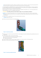
7. Attach the GND lug bracket assembly to your switch using the two removed screws, as shown. Torque the M4 screws to ±8-10 in-lbs. Figure 4. Ground lug assembly attached 8. Attach the other end of the ground wire to your rack ground point. 9. Install your switch into your rack using the Z9264F-ON installation instructions. Four-post rack assembly Due to the chassis weight, the Z9264F-ON switch does not support a two-post rack installation; you must install the switch in a four-post rack. To install in a four-post rack, follow the instructions in your rack frame kit. In a four-post rack, the maximum distance between the front and back vertical posts is 36 inches (91.44 cm); the minimum distance is 24 inches (60.96 cm). Four-post rack mount Rack mounting safety considerations NOTE: To prevent bodily injury when mounting or servicing this unit in a rack, take special precautions to ensure that the system remains stable. The following guidelines are provided to ensure your safety: ● If your chassis is the only unit in the rack, mount it at the bottom of the rack. ● When mounting this unit in a partially filled rack, load the rack from the bottom to the top with the heaviest component at the bottom of the rack. ● If the rack comes with stabilizing devices, install the stabilizers before mounting or servicing the unit in the rack. ● If the chassis ships with blanks, remove the blanks from each slot before lifting the chassis. NOTE: These instructions are a condensed reference. Read the safety instructions in your Safety, Environmental, and Regulatory information booklet before you begin. NOTE: The illustrations in this document are not intended to represent a specific switch. ● Rack loading-Overloading or uneven loading of racks may result in shelf or rack failure, possibly damaging the equipment and causing personal injury. Stabilize racks in a permanent location before loading begins. Mount the components starting at the bottom of the rack, then work to the top. Do not exceed your rack's load rating. ● Power considerations-Connect only to the power source specified on the unit. When you install multiple electrical components in a rack, ensure that the total component power ratings do not exceed the circuit capabilities. Overloaded power sources and extension cords present fire and shock hazards. ● Elevated ambient temperature-If you install the switch in a closed rack assembly, the operating temperature of the rack environment may be greater than the room ambient temperature. Use care not to exceed the 45°C (113°F) maximum ambient temperature of the switch. ● Reduced air flow-Do not compromise the amount of airflow required for safe operation of the equipment. Install the equipment in the rack so that the equipment constantly has the correct amount of airflow surrounding it. 10 Z9264F-ON switch installation
-
 1
1 -
2
-
3
-
4
-
 5
5 -
 6
6 -
 7
7 -
 8
8 -
 9
9 -
 10
10 -
 11
11 -
 12
12 -
 13
13 -
 14
14 -
 15
15
 |
 |
