Denon AVR-4306 Owners Manual - Page 19
Connecting Other Sources - owners manual
 |
View all Denon AVR-4306 manuals
Add to My Manuals
Save this manual to your list of manuals |
Page 19 highlights
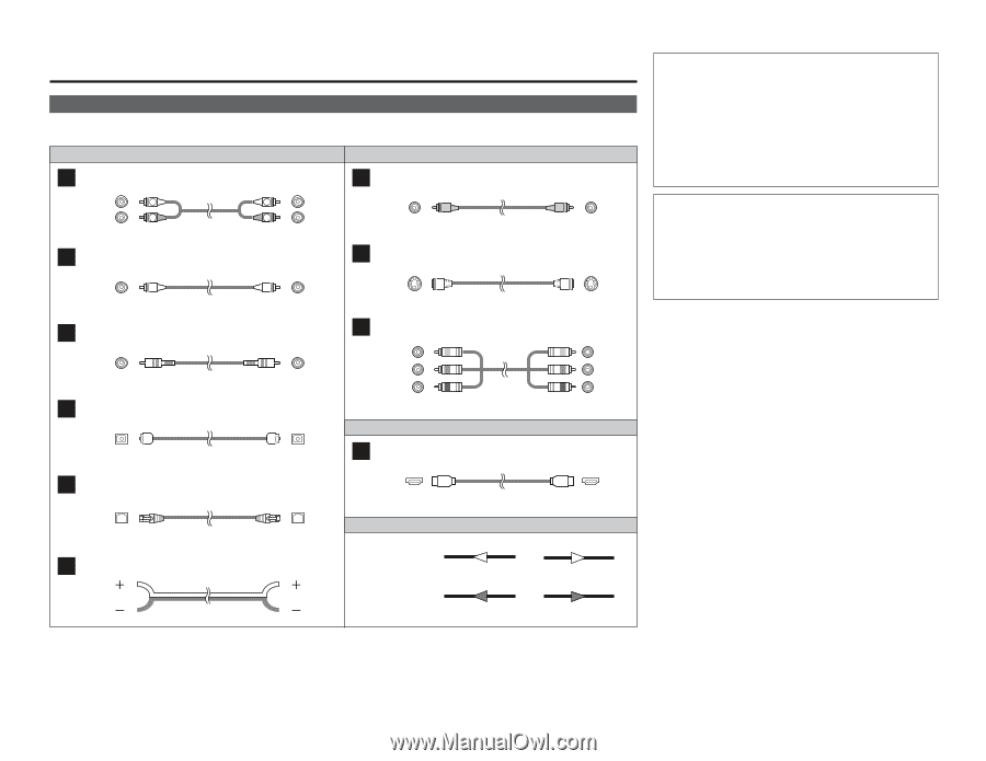
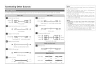
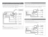
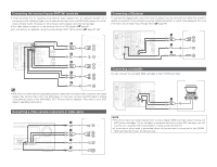
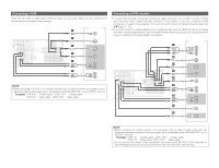
Connecting Other Sources Cable indications The hookup diagrams on the subsequent pages assume the use of the following optional connection cables (not supplied). Audio cable A Analog terminal (Stereo) (White) (Red) L L R R Pin-plug cable B Analog terminal (Monaural, for subwoofer) G Video terminal Video cable (Yellow) Video cable (75 Ω/ohms video pin-plug cable) H S-Video terminal Pin-plug cable C Digital terminal (Coaxial) (Orange) Coaxial cable (75 Ω/ohm pin-plug cable) D Digital terminal (Optical) Optical cable (Optical fiber cable) E DENON LINK terminal DENON LINK cable F Speaker terminal Speaker cable S-Video cable I Component video terminal (Green) (Blue) (Red) Component video cable Audio and Video cable J HDMI terminal (Y) (PB/CB) (PR/CR) HDMI cable Signal direction Audio signal IN OUT OUT IN Video signal IN OUT OUT IN Connecting Other Sources NOTE: • Do not plug in the power supply cord until all connections have been completed. • When making connections, also refer to the operating instructions of the other components. • Be sure to connect the left and right channels properly (left with left, right with right). • Note that binding pin-plug cables together with power supply cords or placing them near a power transformer will result in hum or other noise. NOTE: • Connecting a LD (laser disc) player with a Dolby Digital RF Output. The AVR-4306 does not have a DD RF demodulator function. Therefore, you need to use a commercially available outboard DD RF demodulator and connect its digital output to one of the AVR-4306 available digital inputs. Refer to the demodulator's owner's manual for further information. 14
-
 1
1 -
2
-
3
-
4
-
5
-
6
-
7
-
8
-
9
-
10
-
11
-
12
-
13
-
 14
14 -
 15
15 -
 16
16 -
 17
17 -
 18
18 -
 19
19 -
 20
20 -
 21
21 -
 22
22 -
 23
23 -
 24
24 -
25
-
26
-
27
-
28
-
29
-
30
-
31
-
32
-
33
-
34
-
35
-
36
-
37
-
38
-
39
-
40
-
41
-
42
-
43
-
44
-
45
-
46
-
47
-
48
-
49
-
50
-
51
-
52
-
53
-
54
-
55
-
56
-
57
-
58
-
59
-
60
-
61
-
62
-
63
-
64
-
65
-
66
-
67
-
68
-
69
-
70
-
71
-
72
-
73
-
74
-
75
-
76
-
77
-
78
-
79
-
80
-
81
-
82
-
83
-
84
-
85
-
86
-
87
-
88
-
89
-
90
-
91
-
92
-
93
-
94
-
95
-
96
-
97
-
98
-
99
-
100
-
101
-
102
-
103
-
104
-
105
-
106
-
107
-
108
-
109
-
110
-
111
-
112
-
113
-
114
-
115
-
116
-
117
-
118
-
119
-
120
-
121
-
122
-
123
-
124
-
125
-
126
-
127
-
128
-
129
-
130
-
131
-
132
-
133
-
134
-
135
-
136
-
137
-
138
-
139
-
140
-
141
-
142
-
143
-
144
-
145
-
146
 |
 |