Denon AVR1910 Owners Manual - English - Page 20
Once Connections are, Completed - turns off
 |
UPC - 083795000899
View all Denon AVR1910 manuals
Add to My Manuals
Save this manual to your list of manuals |
Page 20 highlights
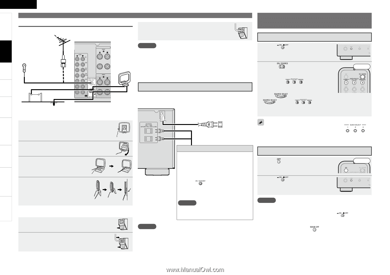
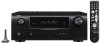
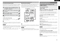
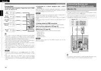
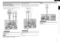
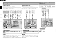
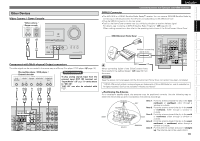
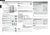
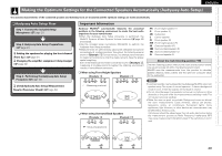
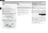
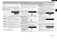
Getting Started Connections Settings Playback Multi-Zone Remote Control Information Troubleshooting Specifications ENGLISH Antenna terminals Direction of broadcasting station FM antenna 75 Ω/ohms Coaxial cable FM indoor antenna (supplied) AM loop antenna (supplied) Connecting Devices not Equipped with HDMI terminals 3 Return the lever. Once Connections are Completed Turning the Power On NOTE • Do not connect two FM antennas simultaneously. • Even if an external AM antenna is used, do not disconnect the AM loop antenna. • Make sure the AM loop antenna lead terminals do not touch metal parts of the panel. Connecting the Power Cord 1 Press . The power indicator lights red and the power is set to the standby mode. 2 Press . The power indicator flashes green and the power turns on. b Also press when in standby mode, the power turns on. Front AM outdoor antenna Ground n AM loop antenna assembly 1 Remove the vinyl tie and take out the connection line. 2 Bend in the reverse direction. 3-1With the antenna on top of any stable surface. Mount 3-2With the antenna attached to a wall. Installation hole Mount on wall, etc. n Connection of AM antennas 1 Push the lever. 2 Insert the conductor. Wait until all connections have been completed before connecting the power cord. Power cord To household power outlet (AC 120 V, 60 Hz) Connection to the AC outlets • These outlets supply power to external au- dio equipment. • Audio equipment with a total power con- sumption of 120 W (1 A) can be connect- ed. • The power supply turns on and off together with the on the main unit. When set to "ON", power is supplied from the outlet. When set to "STANDBY", no power is sup- plied. NOTE When "HDMI Control" (vpage 28) is set to "ON", power is supplied constantly to the AC outlet (UNSWITCHED). NOTE • Insert the AC plugs securely. Incomplete connections could cause noise. • Only use the AC outlets to plug in audio equipment. Do not use them as power supplies for hairdryers or anything other than audio equipment. When has been pressed, the input source set with the is set. If a has been pressed, the input source stored in the memory for the quick select function is set (vpage 50 "Saving frequently used settings (Quick Select Function)"). This operation can also be performed by pressing a on the main unit. Turning the Power Off 1 Press . The power is set to the standby mode. Front 2 Press . The power indicator turns off, and so does the power. NOTE • Power continues to be supplied to some of the circuitry even when the power is in the standby mode. When leaving home for long periods of time or when traveling, either press to turn off the power, or unplug the power cord from the power outlet. • When the ZONE2 power is switched on, and you want to switch off the MAIN ZONE power, press . 17
-
 1
1 -
2
-
3
-
4
-
5
-
6
-
7
-
8
-
9
-
10
-
11
-
12
-
13
-
14
-
 15
15 -
 16
16 -
 17
17 -
 18
18 -
 19
19 -
 20
20 -
 21
21 -
 22
22 -
 23
23 -
 24
24 -
 25
25 -
26
-
27
-
28
-
29
-
30
-
31
-
32
-
33
-
34
-
35
-
36
-
37
-
38
-
39
-
40
-
41
-
42
-
43
-
44
-
45
-
46
-
47
-
48
-
49
-
50
-
51
-
52
-
53
-
54
-
55
-
56
-
57
-
58
-
59
-
60
-
61
-
62
-
63
-
64
-
65
-
66
-
67
-
68
-
69
-
70
-
71
-
72
 |
 |