Denon DCD-425 Service Manual - Page 14
OT IOO
 |
View all Denon DCD-425 manuals
Add to My Manuals
Save this manual to your list of manuals |
Page 14 highlights
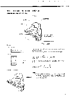
DCD425/335 ADJUSTMENT 1. Adjustment method (1) Necessary equipment for adjustment 1. Dual trace oscilloscope 2. Reference disc TOMITA YASUKO Input (Generator) (CA-1094 or CA-1094A) 3. Oscillator (10 Hz - 10 kHz, 0 - 3 Vp-p) 4. Frequency counter (readable no less than 5 kHz) 5. Lissajous jig Input (Main unit) OSC INPUT Lissajous jig INPUT 22k GND OUTPUT 10k 4700P GND T 0.022µ 4700P 10k Output (Oscilloscope) (2) Location JK251 JK301 JK252 VR102 OO VR101 (TE.G) (TE.8) VR103 (FE.O) TP1 TP5 MAIN UNIT (Component side) TEST POINT 0 TP1: TEO TP2: TEI TP3: FEO TP4: RFO TP5: GND 0 (3) Preset 1. Preset VR101 to 103. 2. Step. FRONT PANEL SIDE I VR103 (Focus offset) 3 O'clock VR101 O (Tracking offset) 3 O'clock 1. Focus offset 2. Tracking offset 3. Tracking gain VR102 (Tracking gain) 3 O'clock 14
-
 1
1 -
2
-
3
-
4
-
5
-
6
-
7
-
8
-
 9
9 -
 10
10 -
 11
11 -
 12
12 -
 13
13 -
 14
14 -
 15
15 -
 16
16 -
 17
17 -
 18
18 -
 19
19 -
20
-
21
-
22
-
23
-
24
-
25
-
26
-
27
-
28
-
29
-
30
-
31
-
32
 |
 |
