Denon DCD-425 Service Manual - Page 15
Adjustment, 1094A, Component
 |
View all Denon DCD-425 manuals
Add to My Manuals
Save this manual to your list of manuals |
Page 15 highlights
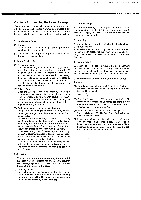
Adjustment Disc: CA-1094 or CA-1094A 1. Focus offset Adjustment 1. Connect an oscilloscope to TP3 (FEO) and TP5 (GND). 2. Insert the disc and set the unit in stop mode. 3.Adjust VR103 so as a DC voltage value on the scope becomes 0 V. DC 0V 0V ±0.05V 2. Tracking offset Adjustment 1. Connect an oscilloscope to TP1 (TEO) and TP5 (GND). 2.Insert the disc and set the unit in play mode. 3.Set VR102 fully counterclockwise. 4.Adjust VR101 and obtain a waveform on the scope becomes A = B. 0V A=B±-0.1V O JK251 JK301 JK252 VR101 (TE.B) VR102 (TE.G) O VR103 (FE.O) / TP1 TP5 TP1: TEO TP2: TEI TP3: FEO TP4: RFO TP5: GND MAIN UNIT (Component side) O O DC0425/335 II= 3. Tracking Gain Adjustment 1. Connect INPUT terminal of Lissajous jig and TP2 (TEI). 2. Connect OUTPUT terminal of Lissajous jig and TP1 (TEO). 3. Connect GND terminal of Lissajous jig and TP5 (GND). 4. Connect OSC INPUT terminal of Lissajous jig and output terminal of generator. 5. Connect GND terminal of Lissajous jig and GND terminal of generator. 6. Connect X, Y terminals of Lissajous jig and X, Y terminals of oscilloscope. 7. Connect GND terminal of Lissajous jig and GND terminal of oscilloscope. 8. Adjust the generator so as to obtain a frequency 1,100 Hz, output 5.0 Vp-p. 9. Load the disc and set the unit in play mode. 10. Adjust VR102 to obtain a waveform on the scope as indicated the following figures. Generator O Oscilloscope 0 -®X OY Range X : 100mV Y : 500mV Main P.W.B. OSC INPUT o TEI INPUT 22k GTNED000GoNuTDpuT 10k Y T 4700P GND 0.022µA 47001: xo 10k Lissajous jig -O TP1(TE0) -O TE2(TEI) O -O TP5(GND) VR102 ■ Tracking Gain Waveform No good (Clockwise gain: Max) Good (Center) No good (Counterclockwise gain: Max) 15
-
 1
1 -
2
-
3
-
4
-
5
-
6
-
7
-
8
-
9
-
 10
10 -
 11
11 -
 12
12 -
 13
13 -
 14
14 -
 15
15 -
 16
16 -
 17
17 -
 18
18 -
 19
19 -
 20
20 -
21
-
22
-
23
-
24
-
25
-
26
-
27
-
28
-
29
-
30
-
31
-
32
 |
 |
