Denon DCM 390 Owners Manual - Page 9
Connections - operating instructions
 |
UPC - 081757506991
View all Denon DCM 390 manuals
Add to My Manuals
Save this manual to your list of manuals |
Page 9 highlights
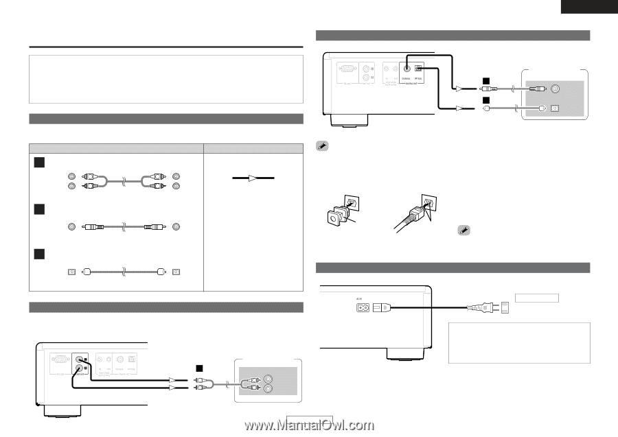
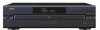
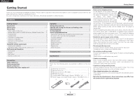
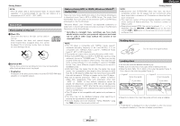
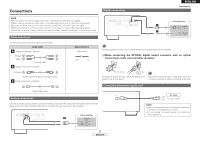
Connections Digital connections ENGLISH Connections NOTE: • Do not plug in the power supply cord until all connections have been completed. • When making connections, also refer to the operating instructions of the other components. • Be sure to connect the left and right channels properly (left with left, right with right). • Making connections with the power turned on could result in noise or damage the speakers. • Bunching the power supply cords and connection cables together could result in humming or noise. Cable indications Connect using the connection cables shown below. Audio cable A Analog connections (Stereo) (White) (Red) L L R R Pin-plug cable B Digital connections (Coaxial) (Orange) Coaxial cable (75 Ω/ohms pin-plug cable) C Digital connections (Optical) Signal direction Audio signal OUT IN CD recorder etc. B COAXIAL IN C OPTICAL IN • Digital signals are output from optical terminal and coaxial terminal with parallel. ¢ When connecting the OPTICAL digital output connector with an optical transmission cable (commercially available) Protective cap Match the shapes Remove the protective cap, match the shapes then insert firmly all the way in. • Store the protective cap in a safe place so as not to lose it, and use it when not using the terminal. Connecting the power supply cord Optical fiber cable Analog connections Use the included pin-plug cable to connect the left (L) and right (R) output terminal (LINE OUT) of the CD Player to the CD, AUX or TAPE PLAY left (L) and right (R) input terminal of the amplifier. Stereo amplifier A AUDIO IN L L L R R R AC outlet AC 120 V, 60 Hz NOTE: • Insert the plugs securely. Incomplete connections will result in the generation of noise. • Do not unplug the power supply cord while the set is operating. 6 ENGLISH
-
 1
1 -
2
-
3
-
 4
4 -
 5
5 -
 6
6 -
 7
7 -
 8
8 -
 9
9 -
 10
10 -
 11
11 -
 12
12 -
 13
13 -
 14
14 -
15
-
16
 |
 |