Denon DRA 395 Owners Manual - Page 8
Connecting the antenna terminals, Connection of AM antennas, AM loop antenna assembly
 |
UPC - 081757504614
View all Denon DRA 395 manuals
Add to My Manuals
Save this manual to your list of manuals |
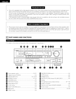
Page 8 highlights
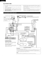
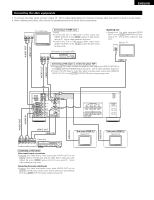
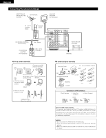
ENGLISH Connecting the antenna terminals DIRECTION OF BROADCASTING STATION FM ANTENNA AM LOOP ANTENNA (An Accessory) 75 Ω/ohms COAXIAL CABLE FEEDER CABLE FM INDOOR ANTENNA (An Accessory) FM ANTENNA ADAPTER (An Accessory) 300 Ω/ohms 300 Ω/ohms TERMINAL LOOP ANT. AM ANTENNA TERMINALS PRE OUT SUB WOOFER FM COAX. 75 ZONE 2 R L ZONE OUT 3 MULTI ROOM R PHONO IN CD SIGNAL GND DVD/ VDP V. AUX ZONE 2 MULTI ROOM ZONE 3 OUT DVD/ VDP IN V. AUX VCR VCR CDR/ TAPE MONITOR OUT VCR VCR OUT CDR/ TAPE IN VIDEO OUT L AUDIO ROOM TO ROOM (REMOTE CONTROL) AM OUTDOOR ANTENNA GROUND AM loop antenna assembly Connect to the AM antenna terminals. 1 2 3 Remove the vinyl tie and take out the Bend in the reverse 4 connection line. direction. a. With the antenna on top any stable surface Mount b. With the antenna attach to a wall. Installation hole Mount on wall, etc. 8 FM antenna adapter assembly Open the Cover PULL PULL CLAMP ANTENNA ADAPTER REMOVE CLAMP 75 Ω/ohms COAXIAL CABLE SHUT 14mm CLAMP 9mm 5mm 3C-2V 19mm 14mm 5mm 5C-2V Connection of AM antennas 1. Push the lever. 2. Insert the conductor. 3. Return the lever. Note to CATV system installer: This reminder is provided to call the CATV system installer's attention to Article 820-40 of the NEC which provides guidelines for proper grounding and, in particular, specifies that the cable ground shall be connected to the grounding system of the building, as close to the point of cable entry as practical. NOTES: • Do not connect two FM antennas simultaneously. • Even if an external AM antenna is used, do not disconnect AM loop antenna. • Make sure AM loop antenna lead terminals do not touch metal parts of the panel.
-
 1
1 -
2
-
 3
3 -
 4
4 -
 5
5 -
 6
6 -
 7
7 -
 8
8 -
 9
9 -
 10
10 -
 11
11 -
 12
12 -
 13
13 -
14
-
15
-
16
-
17
-
18
-
19
-
20
-
21
-
22
-
23
-
24
-
25
-
26
-
27
-
28
-
29
-
30
-
31
-
32
-
33
-
34
-
35
-
36
-
37
-
38
-
39
-
40
-
41
-
42
-
43
-
44
-
45
-
46
-
47
-
48
-
49
-
50
 |
 |
