Dewalt D24000 Instruction Manual - Page 6
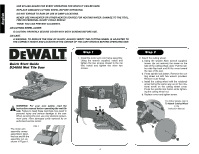
Quick Start Guide, D24000 Wet Tile Saw
 |
View all Dewalt D24000 manuals
Add to My Manuals
Save this manual to your list of manuals |
Page 6 highlights
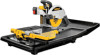
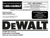
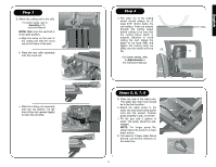
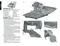
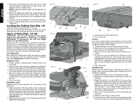
English USE SPLASH GUARD FOR EVERY OPERATION FOR WHICH IT CAN BE USED. REPLACE DAMAGED CUTTING WHEEL BEFORE OPERATING. DO NOT EXPOSE TO RAIN OR USE IN DAMP LOCATIONS. NEVER USE PAN HEATER OR OTHER HEATER SOURCE FOR HEATING WATER. DAMAGE TO THE TOOL, FIRE OR PERSONAL INJURY COULD RESULT. THINK! YOU CAN PREVENT ACCIDENTS. ON CUTTING WHEEL COVER CAUTION: PROPERLY SECURE COVER WITH BOTH SCREWS BEFORE USE. ON CART WARNING: TO REDUCE THE RISK OF INJURY, ALWAYS VERIFY THE CUTTING WHEEL IS ADJUSTED TO THE CORRECT HEIGHT AND LOCATION IN THE CENTER OF THE CART GROOVE BEFORE OPERATING SAW. Quick Start Guide D24000 Wet Tile Saw Step 1 1. Install the motor arm onto frame assembly. Using the wrench supplied, install and tighten the two screws closest to the rail first. Install and tighten the other two screws. WARNING: For your own safety, read the instruction manual before operating the wet tile saw. Failure to heed these warnings may result in personal injury and serious damage to the saw. When servicing this tool, use only identical replacement parts. Have damaged cords replaced by an authorized service center. The motor arm assembly comes assembled. Open the box and lift the assembly out, as shown in Figure 1. FIG. 1 4 Step 2 2. Attach the cutting wheel. a. Using the smaller Allen wrench supplied, loosen (do not remove) the screw on the side of the cutting wheel cover. Pull the rubber side flap back and lift the cover toward the rear of the saw. b. Press spindle lock button. Remove the cutting wheel nut with hex wrench provided. Remove outer flange. c. Install the cutting wheel with the rotational arrow facing the same way as on the rotational arrow on the cutting wheel cover. Press the spindle lock button while tightening the cutting wheel nut. d. Replace cover and tighten screw. For further details, refer to To Attach Cutting Wheel in the Instruction Manual.
-
 1
1 -
 2
2 -
 3
3 -
 4
4 -
 5
5 -
 6
6 -
 7
7 -
 8
8 -
 9
9 -
 10
10 -
 11
11 -
 12
12 -
13
-
14
-
15
-
16
-
17
-
18
-
19
-
20
-
21
-
22
-
23
-
24
-
25
-
26
-
27
-
28
-
29
-
30
-
31
-
32
-
33
-
34
-
35
-
36
-
37
-
38
-
39
-
40
-
41
-
42
 |
 |