Dewalt D55140 Instruction Manual - Page 8
Features - pressure switch
 |
View all Dewalt D55140 manuals
Add to My Manuals
Save this manual to your list of manuals |
Page 8 highlights
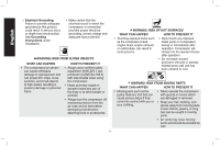
English FEATURES ON (I) /OFF SWITCH (O) Place this switch (A) in the ON position to provide A automatic power to the pressure switch and OFF to remove power at the end of each use. PRESSURE SWITCH The pressure switch automatically starts the motor when the air tank pressure drops below the factory set cut-in pressure. It stops the motor when the air tank pressure reaches the factory set cut-out pressure. SAFETY VALVE If the pressure switch does not shut off the air compressor at its cut-out pressure setting, the safety valve (G) will protect against high pres- sure by popping out at its factory set pressure (slightly higher than the pressure switch cut-out G setting). CHECK VALVE When the air compressor is operating, the check valve is open, allowing compressed air to enter the air tank. When the air compressor reaches cut-out pressure, the check valve closes, allowing air pressure to remain inside the air tank. TANK PRESSURE GAUGE The tank pressure gauge (B) indicates the reserve air pressure in the tank. BDC E OUTLET PRESSURE GAUGE The outlet pressure gauge (C) indicates the air pressure available at the outlet side of the regulator. This pressure is controlled by the regulator and is always less than or equal to the tank pressure. REGULATOR The regulator (D) controls the air pressure shown on the outlet pressure gauge. Turn regulator knob clockwise to increase pressure and counterclockwise to decrease pressure. UNIVERSAL QUICK CONNECT BODY The universal Quick Connect body (E) accepts the three most popular styles of Quick Connect plugs: Industrial, automotive, and ARO. DRAIN VALVE The drain valve (G) is located at the base of the air G tank and is used to drain condensation at the end of each use. See Draining Air Tank under Maintenance. COOLING SYSTEM This compressor contains an advanced design cooling system. It is normal for this fan to blow air through the vent holes in large amounts. The cooling system is working when air is expelled. AIR COMPRESSOR PUMP The pump compresses air into the air tank. Working air is not available until the compressor has raised the air tank pressure above that required at the air outlet. 8
-
 1
1 -
2
-
 3
3 -
 4
4 -
 5
5 -
 6
6 -
 7
7 -
 8
8 -
 9
9 -
 10
10 -
 11
11 -
 12
12 -
 13
13 -
14
-
15
-
16
-
17
-
18
-
19
-
20
-
21
-
22
-
23
-
24
-
25
-
26
-
27
-
28
-
29
-
30
-
31
-
32
-
33
-
34
-
35
-
36
-
37
-
38
-
39
-
40
-
41
-
42
-
43
-
44
-
45
-
46
-
47
-
48
-
49
-
50
-
51
-
52
-
53
-
54
-
55
 |
 |
