Dewalt DCS355D1 Instruction Manual - Page 13
Attaching the Cut Guide Fig. 8-12
 |
View all Dewalt DCS355D1 manuals
Add to My Manuals
Save this manual to your list of manuals |
Page 13 highlights
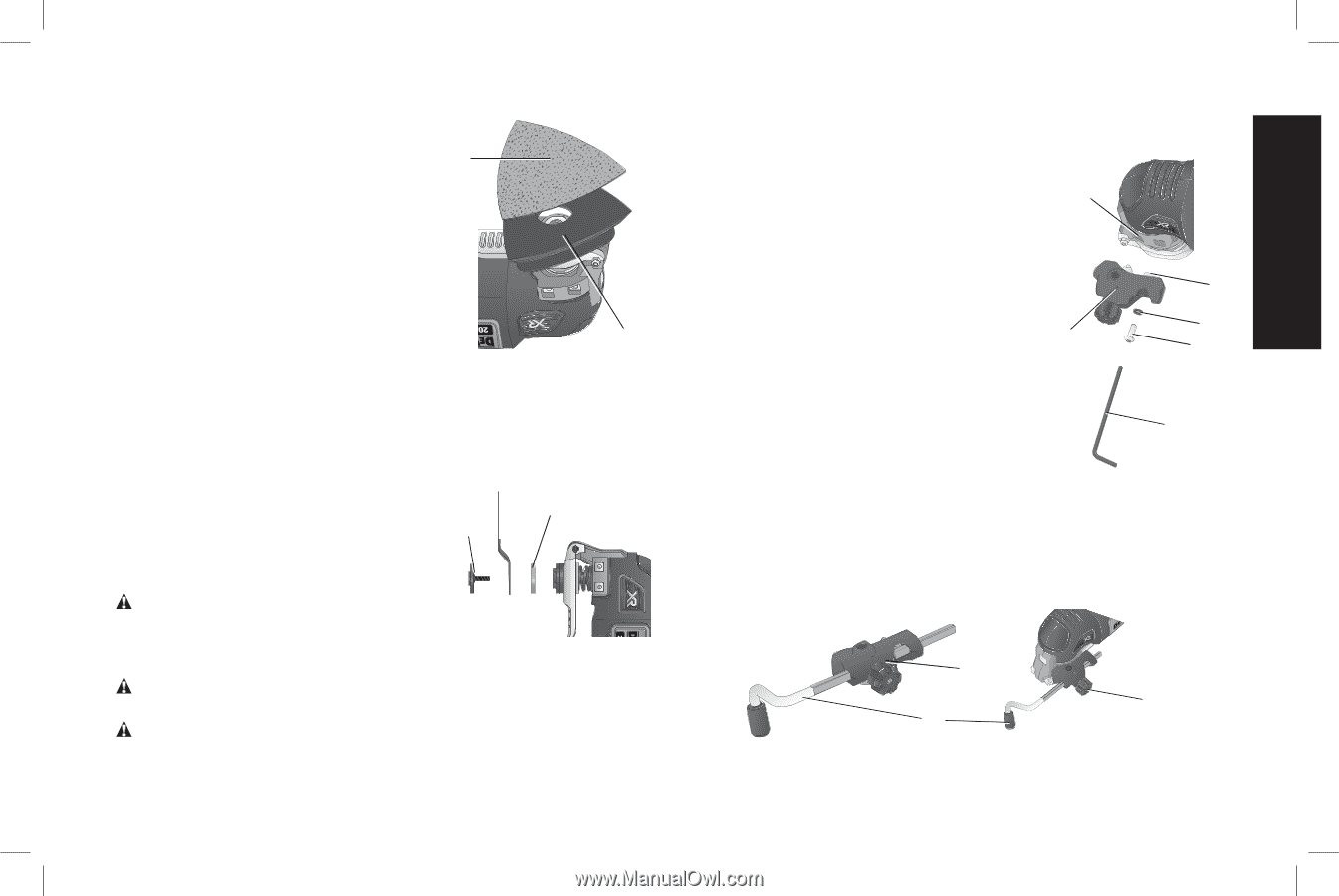
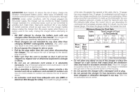
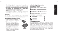
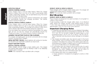
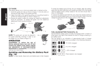
English 2. Align the edges on the sanding FIG. 6 sheet, with the edge of the sanding platen and press the sanding sheet L (L) onto the platen. 3. Firmly press the base with the sanding sheet attached against a flat surface and briefly switch the tool on. This provides for good adhesion between the platen and the sanding sheet and also helps to prevent premature wear. K 4. When the tip of the sanding sheet becomes worn, detach the sheet from the platen, rotate and reapply. ATTACHING ACCESSORIES USING THE UNIVERSAL ADAPTER (FIG. 7) Non-DeWALT accessories can be FIG. 7 attached using the universal adaptor. 1. Place the washer (M) on the tool. 2. Place accessory on to washer. N M 3. Tighten and secure adaptor nut (N) using hex wrench. CAUTION: To avoid injury, do not use any accessory for an application where the adaptor may fail to hold the accessory. CAUTION: Read and follow all manufacturers' safety warnings for any accessories used with this tool. CAUTION: To avoid injury, ensure adaptor and accessory are securely tightened. Attaching the Cut Guide (Fig. 8-12) The depth/cut guide allows you to precisely FIG. 8 cut material at a specified depth or height and more accurately track a marked cut line. E 1. Attach the cut guide block (F) by inserting the tabs (O) on the guide into the accessory side mount (E) on the main body of the tool. 2. Secure the block to the main body with O the supplied screw (Q) and washer (S). S Tighten with the supplied hex wrench (R). F Q DEPTH GUIDE This feature allows you to precisely cut material at a specified depth. 1. Insert the guide arm (G) as shown in R Figure 9 into the front slot on the guide block (F). 2. Adjust the length of the guide by pulling out or pushing inward to achieve the desired cut depth as shown in Figure 10. 3. Secure the guide in place by turning the depth/cut adjustment knob (P) clockwise. To release the guide, turn the depth/cut adjustment knob counterclockwise. FIG. 9 FIG. 10 F P G 11
-
 1
1 -
2
-
3
-
4
-
5
-
6
-
7
-
 8
8 -
 9
9 -
 10
10 -
 11
11 -
 12
12 -
 13
13 -
 14
14 -
 15
15 -
 16
16 -
 17
17 -
 18
18 -
19
-
20
-
21
-
22
-
23
-
24
-
25
-
26
-
27
-
28
-
29
-
30
-
31
-
32
-
33
-
34
-
35
-
36
-
37
-
38
-
39
-
40
-
41
-
42
-
43
-
44
-
45
-
46
-
47
-
48
-
49
-
50
-
51
-
52
-
53
-
54
-
55
-
56
-
57
-
58
-
59
-
60
 |
 |