Dewalt DW712 Parts Diagram - Page 13
Fitting a Mains Plug to 115 V Units - miter saws
 |
View all Dewalt DW712 manuals
Add to My Manuals
Save this manual to your list of manuals |
Page 13 highlights
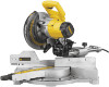
Package Contents The package contains: 1 Assembled mitre saw 1 Blade spanner 1 Saw blade 1 Material clamp 1 Instruction manual 1 Exploded drawing • Check for damage to the tool, parts or accessories which may have occurred during transport. • Take the time to thoroughly read and understand this manual prior to operation. Description (fig. A1-A6) WARNING: Never modify the power tool or any part of it. Damage or personal injury could result. A1 1 On/off switch 2 Moveable lower guard 3 Fence left-hand side 4 Mitre lever 5 Mitre latch 6 Mitre scale 7 Fixed fence 8 Fence right-hand side 9 Bevel position adjustment stop 10 Bevel scale 11 Bevel clamp handle 12 Grooving stop 13 Rail lock knob 14 Head lock down pin 15 Grooving depth adjustment knob 16 Spindle lock button 17 Head lock up release lever 18 Operating handle 19 Speed control dial (DW712) A2 23 Upper guard 24 Dust spout 25 Rails 26 Blade spanner 27 Bevel stop override knob 28 Vertical position adjustment stop 29 Upper fence left-hand side clamping knob 30 Hand indentation 31 Kerf plate 32 Date code OPTIONAL ACCESSORIES A4 35 Legstand A5 36 Dust extraction kit A6 37 Carrying strap INTENDED USE Your DEWALT DW712 Mitre Saw has been designed for professional cutting wood, wood products and plastics. It performs the sawing operations of cross-cutting, bevelling and mitring easily, accurately and safely. ENGLISH This unit is designed for use with a nominal blade diameter 216 mm carbide tip blade. DO NOT use under wet conditions or in presence of flammable liquids or gases. These miter saws are professional power tools. DO NOT let children come into contact with the tool. Supervision is required when inexperienced operators use this tool. WARNING! Do not use the machine for purposes other than intended. • This product is not intended for use by persons (including children) suffering from diminished physical, sensory or mental abilities; lack of experience, knowledge or skills unless they are supervised by a person responsible for their safety. Children should never be left alone with this product. Electrical Safety The electric motor has been designed for one voltage only. Always check that the power supply corresponds to the voltage on the rating plate. Your tool is double insulated in accordance with EN 61029; therefore no earth wire is required. WARNING: 115 V units have to be operated via a fail-safe isolating transformer with an earth screen between the primary and secondary winding. In case of cord replacement the tool must only be repaired by an authorized service agent or by qualified electrician. Mains Plug Replacement (U.K. & Ireland only) If a new mains plug needs to be fitted: • Safely dispose of the old plug. • Connect the brown lead to the live terminal in the plug. • Connect the blue lead to the neutral terminal. WARNING: No connection is to be made to the earth terminal. Follow the fitting instructions supplied with good quality plugs. Recommended fuse: 13 A. Fitting a Mains Plug to 115 V Units (U.K. and Ireland Only) • The plug fitted should be comply with BS EN 60309 (BS4343), 16 Amps, earthing contact position 4h. WARNING: Always ensure that the cable clamp is correctly and securely fitted to the sheath of the cable. Using an Extension Cable If an extension cable is required, use an approved 3-core extension cable suitable for the power input of this tool (see Technical Data).The minimum conductor size is 1.5 mm2; the maximum length is 30 m. When using a cable reel, always unwind the cable completely. Installation UNPACKING (FIG. B) • Remove the saw from the packing material carefully. • Release the rail lock knob (13), and push the saw head back to lock it in the rear position. • Press down the operating handle (18) and pull out the lock down pin (14), as shown. • Gently release the downward pressure and allow the head to rise to its full height. BENCH MOUNTING (FIG. C) • Holes (40) are provided in all four feet to facilitate bench mounting. Two different sized holes are provided to accommodate different sizes of bolts. Use either hole; it is not necessary to use both. Bolts with a diameter of 8 mm and 80 mm in length are suggested. 11
-
 1
1 -
2
-
3
-
4
-
5
-
6
-
7
-
 8
8 -
 9
9 -
 10
10 -
 11
11 -
 12
12 -
 13
13 -
 14
14 -
 15
15 -
 16
16 -
 17
17 -
 18
18 -
19
-
20
 |
 |
