Dewalt DW712 Parts Diagram - Page 16
Quality of Cut, Body and Hand Position - miter saws blades
 |
View all Dewalt DW712 manuals
Add to My Manuals
Save this manual to your list of manuals |
Page 16 highlights
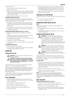
ENGLISH • Depress the head to allow the blade to cut through the timber and enter the plastic kerf plate (31). • After completing the cut, release the switch and wait for the saw blade to come to a complete standstill before returning the head to its upper rest position. PERFORMING A SLIDING CUT (FIG. O) The guide rail allows cutting larger workpieces from 50 x 100 mm up to 500 x 1000 mm using an out-down-back sliding motion. • Release the rail lock knob (13). • Pull the saw head towards you and switch the tool on. • Lower the saw blade into the workpiece and push the head back to complete the cut. • Proceed as described above. WARNING: • Do not perform sliding cuts on workpieces smaller than 50 x 100 mm. • Remember to lock the saw head in the rear position when the sliding cuts are finished. VERTICAL MITRE CROSS-CUT (FIG. A1, P) • Release the mitre lever (4) and depress the mitre latch (5). Move the arm left or right to the required angle. • The mitre latch will automatically locate at 10°, 15°, 22.5°, 31.62° and 45° both left and right, and at 50° left and 60° right. If any intermediate angle is required hold the head firmly and lock by tightening the mitre lever. • Always ensure that the mitre lever is locked tightly before cutting. • Proceed as for a vertical straight cross-cut. WARNING: When mitring the end of a piece of wood with a small off-cut, position the wood to ensure that the offcut is to the side of the blade with the greater angle to the fence; i.e. left mitre, off-cut to the right - right mitre, off-cut to the left. BEVEL CUTS (FIG. A1, A2 & Q) Bevel angles can be set from 48° left to 2° right and can be cut with the mitre arm set between zero and a maximum of 45° mitre position right or left. • Loosen the left side fence clamping knob (29) and slide the upper part of the left side fence (3) to the left as far as it will go. Loosen the bevel clamp handle (11) and set the bevel as desired. • Tighten the bevel clamp handle (11) firmly. • Proceed as for a vertical straight cross-cut. Quality of Cut The smoothness of any cut depends on a number of variables, e.g. the material being cut. When smoothest cuts are desired for moulding and other precision work, a sharp (60 tooth carbide) blade and a slower, even cutting rate will produce the desired results. WARNING: Ensure that the material does not creep while cutting; clamp it securely in place. Always let the blade come to a full stop before raising the arm. If small fibres of wood still split out at the rear of the workpiece, stick a piece of masking tape on the wood where the cut will be made. Saw through the tape and carefully remove tape when finished. Body and Hand Position Proper positioning of your body and hands when operating the mitre saw will make cutting easier, more accurate and safer. • Never place your hands near the cutting area. • Place your hands no closer than 150 mm from the blade. • Hold the workpiece tightly to the table and the fence when cutting. Keep your hands in position until the switch has been released and the blade has completely stopped. • Always make dry runs (without power) before finish cuts so that you can check the path of the blade. • Do not cross your hands. • Keep both feet firmly on the floor and maintain proper balance. • As you move the saw arm left and right, follow it and stand slightly to the side of the saw blade. • Sight through the guard louvres when following a pencil line. CUTTING PICTURE FRAMES, SHADOW BOXES & OTHER FOUR SIDED PROJECTS (FIG. R1 & R2) TRIM MOULDING AND OTHER FRAMES Try a few simple projects using scrap wood until you develop a "feel" for your saw. Your saw is the perfect tool for mitring corners like the one shown in fig. R1. The joint shown has been made using either bevel adjustment. - Using bevel adjustment The bevel for the two boards is adjusted to 45° each, producing a 90° corner. The mitre arm is locked in the zero position. The wood is positioned with the broad flat side against the table and the narrow edge against the fence. - Using mitre adjustment The same cut can be made by mitring right and left with the broad surface against the fence. The two sketches (fig. R1 & R2) are for four side objects only. As the number of sides changes, so do the mitre and bevel angles. The chart below gives the proper angles for a variety of shapes, assuming that all sides are of equal length. For a shape that is not shown in the chart, divide 180° by the number of sides to determine the mitre or bevel angle. No. of sides 4 5 6 7 8 9 10 Angle mitre or bevel 45° 36° 30° 25.7° 22.5° 20° 18° COMPOUND MITRE (FIG. S1 & S2) A compound mitre is a cut made using a mitre angle (fig. R2) and a bevel angle (fig. R1) at the same time. This is the type of cut used to make frames or boxes with slanting sides like the one shown in fig. S1. WARNING: If the cutting angle varies from cut to cut, check that the bevel clamp knob and the mitre lock knob are securely tightened. These knobs must be tightened after making any changes in bevel or mitre. • The chart shown below will assist you in selecting the proper bevel and mitre settings for common compound mitre cuts. To use the chart, select the desired angle "A" (fig. S2) of your project and locate that angle on the appropriate arc in the chart. From that point follow the chart straight down to find the correct bevel angle and straight across to find the correct mitre angle. 45 0 5 10 15 20 25 30 35 40 45 SQUARE BOX 40 40 85 80 75 70 65 60 55 50 SET THIS MITER ANGLE ON SAW ANGLE OF SIDE OF BOX (ANGLE"A") 35 35 45 40 30 6 SIDED BOX 30 35 85 80 75 70 65 60 25 30 25 55 50 85 80 75 70 65 60 55 50 20 15 10 8 SIDED BOX 5 45 40 45 40 35 30 25 20 35 30 25 20 15 15 10 10 5 5 25 20 20 15 15 10 10 5 5 0 5 10 15 20 25 30 35 40 45 SET THIS BEVEL ANGLE ON SAW 14
-
 1
1 -
2
-
3
-
4
-
5
-
6
-
7
-
8
-
9
-
10
-
 11
11 -
 12
12 -
 13
13 -
 14
14 -
 15
15 -
 16
16 -
 17
17 -
 18
18 -
 19
19 -
 20
20
 |
 |