Dewalt DW744XRS Instruction Manual - Page 7
Your Saw Should Be Assembled In The Follow, Ing Order, Adjusting Rip Scale., Assembling The Rip - table saw fence adjustment
 |
View all Dewalt DW744XRS manuals
Add to My Manuals
Save this manual to your list of manuals |
Page 7 highlights
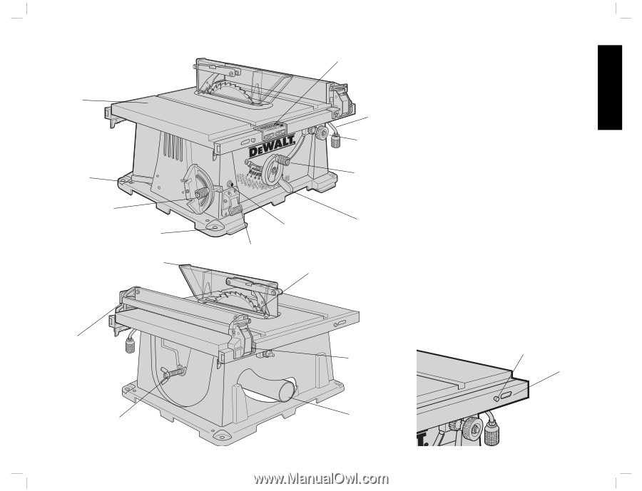
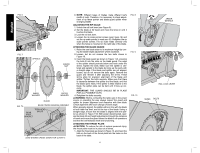
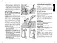
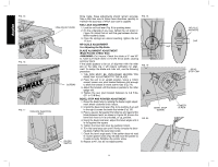
FIG. 3 TABLE SCREW-DOWN HOLES MITER GAUGE MOUNTING HOLES FIG. 4 BLADE GUARD WORK SUPPORT EXTENSION (RETRACTED) BLADE/WRENCH STORAGE RIP SCALE INDICATOR RAIL LOCK LEVER FINE ADJUST KNOB BLADE HEIGHT ADJUSTMENT WHEEL BEVEL LOCK CIRCUIT BREAKER LEVER BUTTON (DW744X ONLY) ON-OFF SWITCH ANTI-KICKBACK TEETH RIP FENCE LATCH YOUR SAW SHOULD BE ASSEMBLED IN THE FOLLOWING ORDER: 1. Blade 2. Rip fence (NOTE: Adjust rip scale before proceeding. See Adjusting Rip Scale.) 3. Blade guard 4. Throat plate Tools needed for assembly include a screwdriver and the wrenches included with your saw ASSEMBLING THE RIP FENCE The rip fence can be installed on the left or right side of your table saw. 1. Locate the pin and opening on fence rails, as shown in Figure 5. Align the pin with the slot and align the latch with the opening. 2. Secure the rip fence by snapping the latches onto the rails as shown in Figure 6. Be sure to snap both latches in place. ATTACHING/REPLACING THE BLADE 1. Raise the saw blade arbor to its maximum height by turning the blade height adjustment wheel clockwise. 2. Remove the arbor nut and flange from the saw arbor by turning counterclockwise. 3. Place the saw blade on to the spindle making sure the teeth of the blade point down at the front of the table. Assemble the washers and arbor nut to the spindle and tighten arbor nut as far as possible by hand, making sure that the saw blade is against the inner washer and the large washer diameters are against the blade. Ensure the side of outer washer marked "Blade Side" is against the blade (see Figure 7). Ensure the spindle and washers are free from dust and debris. 4. To keep the spindle from rotating when tightening the arbor nut, use the open-ended spindle wrench to secure the spindle (see Figure 8). 5. Using the arbor wrench, tighten the arbor nut by turning it clockwise (see Figure 8). FIG. 5 PIN OPENING DUST EXHAUST 5 English
-
 1
1 -
 2
2 -
 3
3 -
 4
4 -
 5
5 -
 6
6 -
 7
7 -
 8
8 -
 9
9 -
 10
10 -
 11
11 -
 12
12 -
13
-
14
-
15
-
16
-
17
-
18
-
19
-
20
-
21
-
22
-
23
-
24
-
25
-
26
-
27
-
28
-
29
-
30
-
31
-
32
-
33
-
34
-
35
-
36
-
37
-
38
-
39
-
40
-
41
-
42
-
43
-
44
 |
 |