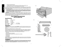
Dewalt DW744XRS Instruction Manual - Page 9
Bench Mounting, Connecting Saw to Power Source, Rip Fence Operation, On-Off Switch, Adjustments - 10 portable table saw
 |
View all Dewalt DW744XRS manuals
Add to My Manuals
Save this manual to your list of manuals |
Page 9 highlights
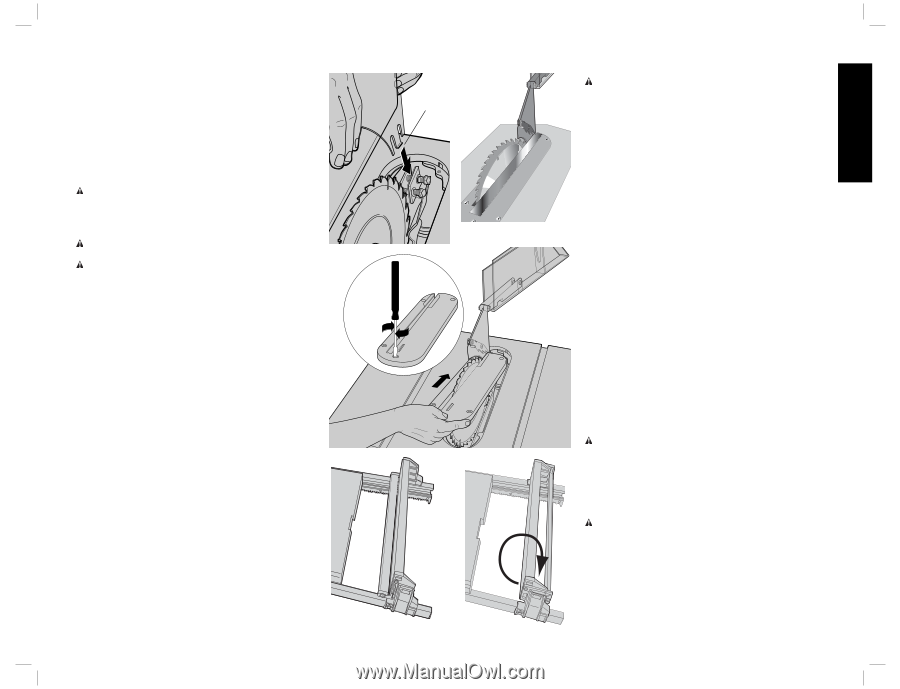
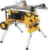
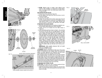
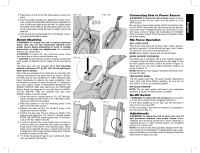
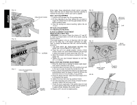
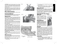
2. Press down on the front of the throat plate to snap it into place. 3. The throat plate includes four adjustment screws which raise or lower the throat plate. When properly adjusted, the front of the throat plate should be flush or slightly below the surface of the table top and secured in place. The rear of the throat plate should be flush or slightly above the table top. 4. Turn the cam lock screw (Detail Fig. 12) clockwise 1/4 turn to lock the throat plate in place. Bench Mounting WARNING: To reduce the risk of serious personal injury, turn unit off and disconnect machine from power source before attempting to move it, change accessories or make any adjustments. An accidental start-up can cause injury. CAUTION: To reduce the risk of personal injury, make sure table saw is firmly mounted before use. CAUTION: Ensure that the surface is stable enough that large pieces of material will not cause it to tip over during use. The table saw must be mounted firmly. The mounting surface must have a 15" by 20" (38 x 51cm) opening to allow dust to escape. Four holes are provided in the tool's feet for mounting. We strongly recommend that these holes be used to anchor the table saw to your workbench or other stationary rigid frame. Alternately, to enhance the saw's portability, it can be mounted to a piece of wood that can be "C" clamped to your work surface, stand or Workmate® Workcenter. The DEWALT DW7440 Table Saw Stand and the DW7440RS Rolling Stand are designed for use with both the DW744 and the DW744X. They are available from your local DEWALT dealer or service center. 1. Center the saw on a square piece of 1/2" (12.7mm) plywood. The plywood must have a 15" x 20" (38 x 51cm) opening to allow dust to escape. 2. Mark the positions of the four mounting holes in the base of the saw with a pencil. 3. Remove the saw and drill 1/4" (6.4mm) holes in the places you have just marked. 4. Position the saw over the four holes you drilled in the plywood and insert four 1/4" (6.4mm) machine screws FROM THE BOTTOM. Install washers and 1/4" (6.4mm) nuts on the top. Tighten securely. 5. In order to prevent the screw heads from marring the surface to which you clamp the saw, attach two strips of scrap wood to the bottom of the plywood base. These strips can be attached with glue, or wood screws can be installed from the top side as long as they don't protrude through the bottom of the strip. 6. "C" clamp the plywood base to your workbench whenever you want to use the saw. FIG. 11A FIG. 12 FIG. 13 FIG. 11B EDGE OF SPLITTER FIG. 14 7 Connecting Saw to Power Source WARNING: To reduce the risk of injury, before connecting saw to power source, make sure the switch is in the OFF position. Be sure your power supply agrees with the nameplate marking. AC ONLY means that your saw will operate on alternating current only. A voltage decrease of 10 percent or more will cause a loss of power and overheating. All DEWALT tools are factory tested. If this tool does not operate, check the power supply. Rip Fence Operation RAIL LOCK LEVER The rail lock lever locks the rip fence rails in place, preventing their movement. To lock the rail lock lever, push it down. To unlock the lever, pull it up (see Figure 9). NOTE: When ripping, always lock the rail lock lever. WORK SUPPORT EXTENSION Your table saw is equipped with a work support extension to support work that extends beyond the saw table. To use the work support extension, rotate it as shown in Figure 13. When not in use, the work support extension retracts, as shown in Figure 14. NOTE: Retract the work support extension whenever working over the table. FINE ADJUST KNOB The fine adjust knob (Fig. 15) allows smaller adjustments when setting the fence. Before adjusting, be sure the rail lock lever is in its up, or unlocked, position. RIP SCALE POINTER NOTE: The rip scale pointer will need to be readjusted whenever a thicker or thinner blade is installed. On-Off Switch WARNING: To reduce the risk of injury, be sure switch is in the OFF position before plugging machine in. Lift the switch paddle up to turn your saw ON and push it down to turn your saw OFF. A hole is provided in the switch for insertion of a padlock to lock the saw off (Fig. 17). Adjustments WARNING: To reduce the risk of injury, turn unit off and disconnect machine from power source before installing and removing accessories, before adjusting or changing set-ups or when making repairs. An accidental start-up can cause injury. NOTE: Your saw is fully and accurately adjusted at the factory at the time of manufacture. If readjustment due to shipping and handling or any other reason is required, follow the steps below to adjust your saw. English
-
 1
1 -
2
-
3
-
 4
4 -
 5
5 -
 6
6 -
 7
7 -
 8
8 -
 9
9 -
 10
10 -
 11
11 -
 12
12 -
 13
13 -
 14
14 -
15
-
16
-
17
-
18
-
19
-
20
-
21
-
22
-
23
-
24
-
25
-
26
-
27
-
28
-
29
-
30
-
31
-
32
-
33
-
34
-
35
-
36
-
37
-
38
-
39
-
40
-
41
-
42
-
43
-
44
 |
 |