Dewalt DWE575SB Instruction Manual - Page 8
Save These Instructions For, Future Use, Motor, Components Fig. 1
 |
View all Dewalt DWE575SB manuals
Add to My Manuals
Save this manual to your list of manuals |
Page 8 highlights
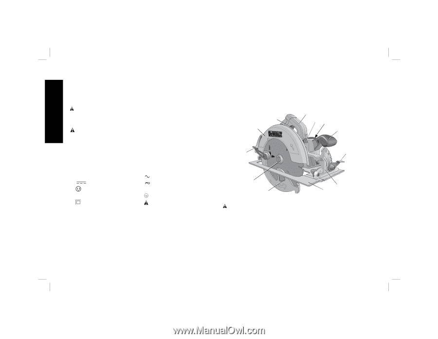
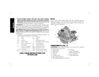
English • Avoid prolonged contact with dust from power sanding, sawing, grinding, drilling, and other construction activities. Wear protective clothing and wash exposed areas with soap and water. Allowing dust to get into your mouth, eyes, or lay on the skin may promote absorption of harmful chemicals. WARNING: Use of this tool can generate and/or disperse dust, which may cause serious and permanent respiratory or other injury. Always use NIOSH/OSHA approved respiratory protection appropriate for the dust exposure. Direct particles away from face and body. WARNING: Always wear proper personal hearing protection that conforms to ANSI S12.6 (S3.19) during use. Under some conditions and duration of use, noise from this product may contribute to hearing loss. • The label on your tool may include the following symbols. The symbols and their definitions are as follows: V volts A........ amperes Hz ......... hertz W....... watts min .......minutes ..... alternating current ....direct current ..... alternating or direct current .........Class I Construction no...... no load speed grounded) ...... earthing terminal .........Class II Construction ....... safety alert symbol double insulated) BPM .. beats per minute .../min ..per minute RPM .. revolutions per minute IPM.......impacts per minute sfpm .. surface feet per minute SAVE THESE INSTRUCTIONS FOR FUTURE USE Motor Be sure your power supply agrees with the nameplate marking. Voltage decrease of more than 10% will cause loss of power and overheating. DEWALT tools are factory tested; if this tool does not operate, check power supply. FIG. 1 B A CD L E K F J G I H COMPONENTS (Fig. 1) WARNING: Never modify the power tool or any part of it. Damage or personal injury could result. A. Trigger switch H. Foot plate B. Main handle I. Lower blade guard C. Blade lock J. Blade clamping screw D. End cap K. Lower guard lever E. Auxiliary handle L. Upper blade guard F. Bevel adjustment lever G. Bevel angle adjustment mechanism 6
-
 1
1 -
2
-
 3
3 -
 4
4 -
 5
5 -
 6
6 -
 7
7 -
 8
8 -
 9
9 -
 10
10 -
 11
11 -
 12
12 -
 13
13 -
14
-
15
-
16
-
17
-
18
-
19
-
20
-
21
-
22
-
23
-
24
-
25
-
26
-
27
-
28
-
29
-
30
-
31
-
32
-
33
-
34
-
35
-
36
-
37
-
38
-
39
-
40
-
41
-
42
-
43
-
44
-
45
-
46
-
47
-
48
-
49
-
50
-
51
-
52
-
53
-
54
-
55
-
56
-
57
-
58
-
59
-
60
 |
 |