Dewalt DWE7491RS Instruction Manual - Page 12
Ripping Fig. 33, On-Off Switch Fig. 29, Guard Operating Feature Fig. 30, Rip Fence Operation Fig. 31 - 10
 |
View all Dewalt DWE7491RS manuals
Add to My Manuals
Save this manual to your list of manuals |
Page 12 highlights
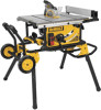
English On-Off Switch (Fig. 29) FIG. 29 WARNING: To reduce the risk of injury, be sure the switch is in the OFF position before plugging machine in. Push green button (H) in to turn this saw on and push down the red paddle to turn this saw off. LOCK OFF FEATURE INSTRUCTIONS A cover above the switch folds down for insertion of a padlock to lock the saw off. A padlock with a maximum diameter of 1/4" (6.35 mm) and minimum clearance of 3" (76.2 mm) is H recommended. Guard Operating Feature (Fig. 30) WARNING: To reduce the risk of injury, turn unit off and disconnect machine from power source before installing and removing accessories, before adjusting or changing setups or when making repairs. An accidental start-up can cause injury. 1. The guard(s) will lock in place when in the raised position. 2. This feature increases visability when measuring the blade to fence distance. 3. Push down on guard(s) and they will release to the operating position. NOTE: Pull on the anti-kickback assembly to ensure it is locked in place. ALWAYS make sure both guards are in the down position in contact with the table before operating. FIG. 30 RAISED POSITION OPERATING POSITION Rip Fence Operation (Fig. 31, 32) RAIL LOCK LEVER (FIG. 31) The rail lock lever (E) locks the fence in place preventing movement during cutting. To lock the rail lever, push it down and toward the rear of the saw. To unlock, pull it up and toward the front of the saw. NOTE: When ripping, always lock the rail lock lever. WORK SUPPORT EXTENSION/NARROW RIPPING FENCE The table saw is equipped with a narrow ripping fence that also supports work that extends beyond the saw table. To use the narrow ripping fence in the work support position, rotate it from its stored position as shown in Figure 32, and slide the pins into the lower sets of slots on both ends of the fence. To use the narrow ripping fence in the narrow ripping position, snap the pins into the upper sets of slots on both ends of the fence. This feature will allow 2" (51 mm) of extra clearance to the blade. If more clearance is necessary, follow directions for making an auxiliary fence under Narrow Rip Auxiliary Fence in the Operation section. NOTE: When not in use, the narrow ripping fence should be placed in its stored position. FIG. 31 FIG. 32 E D NOTE: This fence will allow the guard to remain on the saw when completing narrow ripping. This fence will provide ample space for a push stick. If you prefer more clearance for push blocks or push sticks, refer to Narrow Rip Auxiliary Fence. FINE ADJUSTMENT KNOB (FIG. 31) The fine adjustment knob (D) allows smaller adjustments when setting the fence. Before adjusting, be sure the rail lock lever is in its up or unlocked position. RIP SCALE POINTER The rip scale pointer will need to be adjusted for proper performance of the rip fence if the user switches between thick and thin kerf blades. The rip scale pointer only reads correctly for position 1 (0 to 24.5"), however for position 1 with narrow rip fence in use add 2" (50 mm). See Adjusting the Rip Scale under Assembly. Ripping (Fig. 33) WARNING: Never touch the "free end" of the workpiece or a "free piece" that is cut off, while the power is ON and/or the saw blade is rotating. Piece may contact the blade resulting in a thrown workpiece and possible injury. WARNING: A rip fence should ALWAYS be used for ripping operations to prevent loss of control and personal injury. NEVER perform a ripping operation freehand. ALWAYS lock the fence to the rail. WARNING: When bevel ripping and whenever possible, place the fence on the side of the blade so that the blade is tilted away from the fence and hands. WARNING: Keep hands clear of the blade. WARNING: Use a push stick to feed the workpiece if there is 2-6" (51-152 mm) between the fence and the blade. Use a narrow ripping fence feature and push block to feed the workpiece if there is 2" (51 mm) or narrower between the fence and the blade. 1. Lock the rip fence by pressing the rail lock lever down. Remove the miter gauge. 2. Raise the blade so it is about 1/8" (3.2 mm) higher than the top of the workpiece. 3. Hold the workpiece flat on the table and against the fence. Keep the workpiece about 1" (25.4 mm) away from the blade. 10
-
 1
1 -
2
-
3
-
4
-
5
-
6
-
 7
7 -
 8
8 -
 9
9 -
 10
10 -
 11
11 -
 12
12 -
 13
13 -
 14
14 -
 15
15 -
 16
16 -
 17
17 -
18
-
19
-
20
-
21
-
22
-
23
-
24
-
25
-
26
-
27
-
28
-
29
-
30
-
31
-
32
-
33
-
34
-
35
-
36
-
37
-
38
-
39
-
40
-
41
-
42
-
43
-
44
-
45
-
46
-
47
-
48
-
49
-
50
-
51
-
52
-
53
-
54
-
55
-
56
 |
 |
