EVGA 132-LF-E655-KR User Guide - Page 15
Securing the Motherboard into a System Case
 |
UPC - 843368011703
View all EVGA 132-LF-E655-KR manuals
Add to My Manuals
Save this manual to your list of manuals |
Page 15 highlights
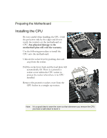
Securing the Motherboard into a System Case Most system cases have a base with mounting studs or spacers to allow the motherboard to be secured to the chassis and help to prevent short circuits. If there are studs that do not align with a mounting hole on the motherboard, it is recommended that you remove that stud to prevent the possibility of a short circuit. In most cases, it is recommended to secure the motherboard using a minimum of nine (9) spacers and screws. 1. Carefully place the motherboard onto the stand offs located inside the chassis. 2. Align the mounting holes with the stand offs. 3. Align the connectors to the I/O shield. 4. Ensure that the fan assembly is aligned with the chassis vents according to the fan assembly instruction. 5. Secure the motherboard with a recommended minimum of nine (9) screws. Connecting Cables This section takes you through all the necessary connections on the motherboard. This will include: Power Connections 24-pin ATX power (PW1) 8-pin ATX 12V power (PW12) Internal Headers Front panel IEEE 1394a USB Headers Audio Serial ATA II USB 2.0 Expansion slots CMOS Clear Button
-
 1
1 -
2
-
3
-
4
-
5
-
6
-
7
-
8
-
9
-
 10
10 -
 11
11 -
 12
12 -
 13
13 -
 14
14 -
 15
15 -
 16
16 -
 17
17 -
 18
18 -
 19
19 -
 20
20 -
21
-
22
-
23
-
24
-
25
-
26
-
27
-
28
-
29
-
30
-
31
-
32
-
33
-
34
-
35
-
36
-
37
-
38
-
39
-
40
-
41
-
42
-
43
-
44
-
45
-
46
 |
 |
