EVGA 132-YW-E179-TR User Guide - Page 13
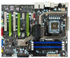
EVGA nForce 790i SLI FTW Motherboard Layout - lga 775 nvidia nforce 790i sli atx intel motherboard
 |
View all EVGA 132-YW-E179-TR manuals
Add to My Manuals
Save this manual to your list of manuals |
Page 13 highlights
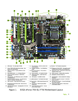
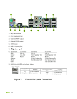
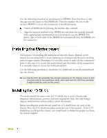
21 21 23 23 7 22 22 22 12 25 26 20 27 11 19 18 11 7 29 7 17 16 16 15 14 13 24 7 11 10 9 8 11 7 6 5 28 1 2 3 4 1. CPU Socket - For Intel LGA 775 CPUs 2. nForce 790i SLI SPP with Active Cooling - Also known as the Northbridge 3. CPU fan connector - Connect CPU Fan to this connector 4. DDR3 DIMM slots 0 - 3 - For System Memory 5. 24-pin ATX power connector - Main Power Connection 6. IDE connector - For IDE devices such as a CD-ROM or Hard Disk Drive 7. Serial-ATA (SATA) connectors - For SATA devices such as a CD-ROM or Hard Disk Drive 8. FDD connector - Floppy Disk Drive Connector 9. NVIDIA MCP (passive heat sink) - Also known as the Southbridge 10. LED POST Code Readout - See Appendix A. for Code Descriptions 11. Fan connectors - Connect auxiliary fans to these headers 12. HD Audio Connector - For Hi-Definition Audio 13. Front panel connector - For use with a system chassis 14. Serial connector - For Serial Port Cable 15. CMOS Clear Button - Easily clears the system BIOS 16. USB headers - For USB Port Cable 17. 1394a connector - For Firewire Port Cable 18. Power button - With integrated power LED indicator 19. Reset button - With integrated HDD activity LED 20. Front panel Audio connector - For use with a system chassis 21. PCI slots - For PCI based components 22. PCI Express x16 slots (SLI) - For graphics cards, multiple slots are used for SLI configurations 23. PCI Express x1 slot - Exclusive for devices that require a PCI-E x1 slot 24. SPDIF connector - Digital Audio connection 25. Backpanel connectors (Figure 2) 26. Heat dissipater - Passive heatsink for Voltage Regulators 27. 8-pin ATX_12V power connector - CPU 8-Pin Power connector 28. MCP/SPP fan connector - Connect Northbridge fan to this connector 29. Motherboard CMOS Battery - Helps retain system BIOS settings Figure 1. EVGA nForce 790i SLI FTW Motherboard Layout
-
 1
1 -
2
-
3
-
4
-
5
-
6
-
7
-
 8
8 -
 9
9 -
 10
10 -
 11
11 -
 12
12 -
 13
13 -
 14
14 -
 15
15 -
 16
16 -
 17
17 -
 18
18 -
19
-
20
-
21
-
22
-
23
-
24
-
25
-
26
-
27
-
28
-
29
-
30
-
31
-
32
-
33
-
34
-
35
-
36
-
37
-
38
-
39
-
40
-
41
-
42
-
43
-
44
-
45
-
46
-
47
-
48
-
49
-
50
-
51
-
52
-
53
-
54
-
55
-
56
-
57
-
58
-
59
-
60
-
61
-
62
-
63
-
64
-
65
-
66
-
67
-
68
-
69
-
70
-
71
-
72
-
73
-
74
-
75
-
76
-
77
-
78
-
79
-
80
-
81
-
82
-
83
-
84
 |
 |
