Electrolux E30EW85GPS Installation Instructions - Page 5
Remove the oven door, Remove the bottom trim - weight
 |
UPC - 057112096353
View all Electrolux E30EW85GPS manuals
Add to My Manuals
Save this manual to your list of manuals |
Page 5 highlights
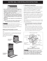
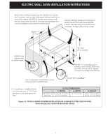
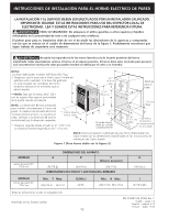
ELECTRIC WALL OVEN INSTALLATION INSTRUCTIONS Frame grounded through the neutral. If used in a mobile home, new branch circuit (1996 NEC) recreational vehicles or where local codes do not permit grounding through neutral see figure 4. 2. If used in mobile homes or if local codes DO NOT permit connection of the frame grounding conductor to the neutral (white) wire, separate the white and bare copper ground wires that extend out of the end of the supply cable of the appliance. Connect the white wire from supply cable to the neutral white wire in the junction box. Connect the black and red wires from the supply cable to the matching color wires in the junction box. The bare wire must now be used to ground the appliance in accordance with local electrical codes. Connect the bare copper ground wire to the grounded lead in the service panel. DO NOT ground to a gas supply pipe. DO NOT connect to electrical power supply until appliance is permanently grounded. Connect the ground wire before turning on the power (Figure 4). Cable from Power Supply Ground Wire Red Wires White Wire 4. Remove the oven door Remove the doors to reduce the weight of the appliance and to facilitate its handling and its installation. IMPORTANT Do not lift the oven by the door handle. To remove the oven door see following steps: 1. Open the door to the fully opened position (Figure 5). 2. Pull up the lock located on each hinge toward the front of range. You may have to apply a little upward pressure on the lock to pull it up (Figure 6). 3. Grasp the door by the sides, pull the bottom of the door up and toward you to disengage the hinge supports. Keep pulling the bottom of the door toward you while rotating the top of the door toward the appliance to completely disengage the hinge levers (Figure 7). 4. Proceed in reverse to replace the oven door. Make sure the hinge supports are fully engaged before unlocking the hinge levers. NOTE: The oven door is very heavy. Be sure to have a firm grip before lifting the oven door off the hinges. Use caution once the door is removed. Do not lay door on its handle. This could cause dents or scratches. Ground Wire (Bare or Green Wire) Black Wires White Wire Junction Box U.L.-Listed Conduit Connector (or CSA listed) Cable from appliance Figure 4 4-WIRE GROUNDED JUNCTION BOX Lock in normal position Figure 5 Lock engaged for door removal Figure 6 If connecting to a 4-wire electrical system, the appliance frame MUST NOT be connected to the neutral wire of the 4-wire electrical system. NOTE TO ELECTRICIAN: The armored cable leads supplied with the appliance are CSA-recognized for connection to larger gauge household wiring. The insulation of the leads is rated at temperatures much higher than temperature rating of household wiring. The current carrying capacity of the conductor is governed by the temperature rating of the insulation around the wire, rather than the wire gauge alone. Figure 7 Hinge Slot - Door removed from the appliance 5. Remove the bottom trim Remove the bottom trim from the top of the unit. This trim will be installed later 5
-
 1
1 -
 2
2 -
 3
3 -
 4
4 -
 5
5 -
 6
6 -
 7
7 -
 8
8 -
 9
9 -
 10
10 -
 11
11 -
12
-
13
-
14
-
15
-
16
-
17
-
18
-
19
-
20
-
21
-
22
-
23
-
24
-
25
-
26
-
27
-
28
 |
 |
