Electrolux E30MC75JSS Installation Instructions - Page 1
Electrolux E30MC75JSS Manual
 |
View all Electrolux E30MC75JSS manuals
Add to My Manuals
Save this manual to your list of manuals |
Page 1 highlights
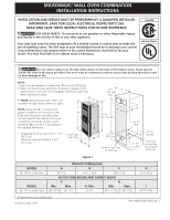
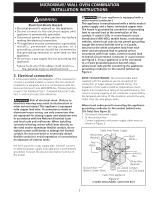
MICROWAVE/ WALL OVEN COMBINATION INSTALLATION INSTRUCTIONS INSTALLATION AND SERVICE MUST BE PERFORMED BY A QUALIFIED INSTALLER. IMPORTANT: SAVE FOR LOCAL ELECTRICAL INSPECTOR'S USE. READ AND SAVE THESE INSTRUCTIONS FOR FUTURE REFERENCE. FOR YOUR SAFETY: Do not store or use gasoline or other flammable vapors and liquids in the vicinity of this or any other appliance. Your new wall oven has been designed to fit a limited variety of cutout sizes to make the job of installing easier. The first step of your installation should be to measure your current cutout dimensions and compare them to the cutout dimensions chart below for your model. You may find little or no cabinet work is necessary. Canada United States Do not remove spacers on the side walls and/or on the back of the built-in oven. These spacers center the oven in the space provided. The oven must be centered to prevent excess heat buildup that may result in heat damage or fire. NOTE: 1. Base must be capable of supporting 350 pounds (158.8 kg). 2. Make sure base is level and front of cabinet is square. If the cabinet base is not level, the oven glides will tend to slide out when opening the door. ** NOTE: Allow at least 23¼" (59.1 cm) C clearance for door depth when it is open. 21/2" I (6.4 cm) Min. NOTE: Dimension G is critical to the proper installation of the built-in oven. If the oven decorative moulding does not butt against the cabinet, or if noise is heard on convection models, verify dimension G to assure it is according to the required dimension. B F 45 5/16" (115.1 cm) H Spacer * Suggested distance from floor is 11½" ** Door Open (29.2 cm). Minimum required distance is 4½" (see note) D (11.4 cm). A 111/2"* (29.2 cm) Bottom edge must be finish-cut G Hole for cable. 3" (7.6 cm) Max. 2" (5.1 cm) Min. Electrical Junction Box (not supplied with unit) Figure 1 MODEL 30" (76.2cm) Wall Oven MODEL 30" (76.2cm) Wall Oven PRODUCT DIMENSIONS A B C 30 (76.2) 46 5/8 (118.4) 28¼ (71.8) CUTOUT DIMENSIONS AND CABINET WIDTH F H Min. Max. G. Min. Min. Max. 28½ (72.4) 29 (73.7) 24 (61) 451/2 (115.8) 46 (115.6) D 24 5/8 (62.5) I 30 (76.2) Min All dimensions are in inches (cm). Printed in United States P/N 318201538 (1007) Rev. C 1
-
 1
1 -
 2
2 -
 3
3 -
 4
4 -
 5
5 -
 6
6 -
 7
7 -
8
 |
 |