Electrolux E30MC75JSS Installation Instructions - Page 5
cabinet and the appliance to prevent tipping
 |
View all Electrolux E30MC75JSS manuals
Add to My Manuals
Save this manual to your list of manuals |
Page 5 highlights
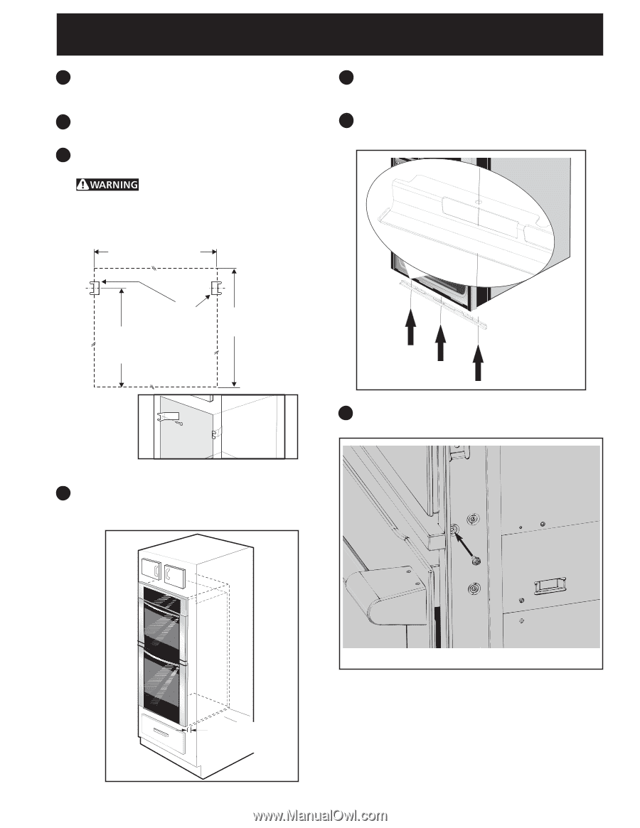
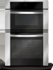
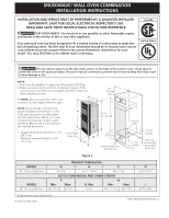
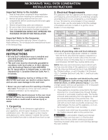
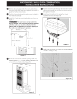
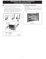
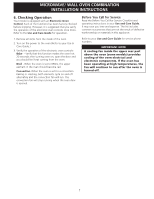
MICROWAVE/ WALL OVEN COMBINATION INSTALLATION INSTRUCTIONS 3 Remove all packaging inside the ovens and remove the lower oven racks and their supports (see owner's guide for further instructions). 4 Find the 2 mounting brackets and screws included in the literature package. 5 Install the 2 anti-tip mounting brackets as shown on figure 7. The wall oven can tip when the door is opened. The mounting brackets supplied with the wall oven must be attached to the cabinet and the appliance to prevent tipping of the wall oven and injury to persons. F (see Fig. 1) 7 Pull the armored cable through the hole for it in the cabinet and toward the junction box while moving the appliance inward. 8 Install now the bottom trim using the screws supplied with the unit (Figure 9). Mounting Brackets 40 5/16" (102.4 cm) H (see Fig. 1) Figure 9 9 Install now the center trim using the screws supplied with the unit (Figure 10). Figure 7 6 Insert the unit into the cabinet opening. Slide unit inward leaving 1½" (3.8 cm) clearance between the unit and front of cabinet (see Figure 8). 1½" (3.8 cm) clearance between unit Figure 8 5 Figure 10
-
 1
1 -
 2
2 -
 3
3 -
 4
4 -
 5
5 -
 6
6 -
 7
7 -
 8
8
 |
 |