Electrolux E36DF76GPS Installation Instructions - Page 5
Electrical Connection to the Range, US models only, Three Conductor Wire Connection, to the Range - installation instructions
 |
UPC - 057112098548
View all Electrolux E36DF76GPS manuals
Add to My Manuals
Save this manual to your list of manuals |
Page 5 highlights
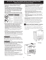
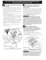
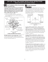
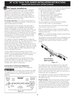
30" & 36" DUAL FUEL RANGE INSTALLATION INSTRUCTIONS (Model with Electric Oven and Gas Cooktop) 5. Electrical Connection to the Range (US models only) This appliance is manufactured with the neutral terminal connected to the range. You may not ground the oven through the neutral (white) wire if oven is used in a new branch circuit installation (1996 NEC), mobile home, recreational vehicle, or where local codes do not permit grounding through the neutral (white) wire. When grounding through the neutral (white) wire is prohibited, you must use a 4-wire power supply cable. See Section 5B. Failure to heed this warning may result in electrocution or other serious personal injury. While connecting range, do not loosen the nuts which secure the terminal block to the range. Electrical failure or loss of electrical connection may occur. 5.A Three Conductor Wire Connection to the Range (The 3-conductor cord or cable must be replaced with a 4-conductor cord or cable where grounding through the neutral conductor is prohibited in new installations, mobile homes, recreational vehicles or in other areas where local codes do not permit neutral grounding) Rear wire access panel Pressure regulator location Figure 8 - 36" Range 2. Remove the 3 loose nuts on the terminal block using 3/8" nut driver or socket. 3. Connect the neutral white wire of the power supply cord to the center silver-colored terminal of the terminal block, and connect the other wires to the outer terminals. Match terminal and power supply wires by color. 4. Replace the 3 nuts on the terminal block (Figure 9). 5. Replace the rear access cover or panel using the screws removed on step 1. If local codes permit connection of the frame grounding conductor to the neutral wire of the power supply cord (Figure 9): 1. Remove the screws at the lower end of the rear wire access panel or cover, then remove the access cover or lift the lower part of the access panel to expose range terminal connection block (Fig. 7 or 8). Rear wire Pressure regulator access cover location Figure 7 - 30" Range Figure 9 Three Conductor or Wire Connection to Range Risk of fire or electrical shock exists if an incorrect size range cord kit is used, if the Installation Instructions are not followed, or if the strain relief bracket is discarded. 5
-
 1
1 -
 2
2 -
 3
3 -
 4
4 -
 5
5 -
 6
6 -
 7
7 -
 8
8 -
 9
9 -
 10
10 -
 11
11 -
12
-
13
-
14
-
15
-
16
-
17
-
18
-
19
-
20
-
21
-
22
-
23
-
24
-
25
-
26
-
27
-
28
-
29
-
30
-
31
-
32
-
33
-
34
-
35
-
36
 |
 |
