Electrolux EI30DS5CJS Installation Instructions (All Languages) - Page 11
Check Operation, Leveling the Range
 |
View all Electrolux EI30DS5CJS manuals
Add to My Manuals
Save this manual to your list of manuals |
Page 11 highlights
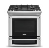
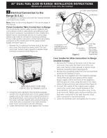
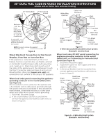
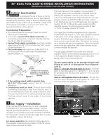
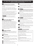
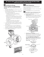
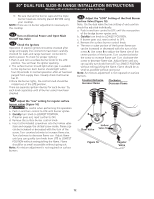
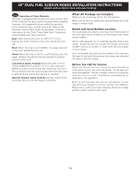
30" DUAL FUEL SLIDE-IN RANGE INSTALLATION INSTRUCTIONS (Models with an Electric Oven and a Gas Cooktop) 9 Leveling the Range Models Equipped with Leveling Device Level the range after installation in the cutout opening. 1. Open the range drawer. The leveling screws control the height of the rear leg. 2. Adjust the appliance legs and wheels as follows until the underside of the cooktop surface is sitting level on the countertop (Figure 12). a. To adjust the front legs, use a wrench on the leg base and turn clockwise to lower or counterclockwise to raise. b.Remove the rear legs using a wrench on the leg base and turn counterclockwise until the legs are removed from the unit. You can discard those legs, they are only in place to solidify the unit for the transport. c. To adjust the rear wheels, use a ratchet or a nutdriver and turn the leveling screws counterclockwise to lower or clockwise to raise. 3. Check if the range is level by installing an oven rack in the center of the oven and placing a level on the rack (Figure 13). 4. Take 2 readings with the level placed diagonally in one direction and then the other. Level the range, if necessary, by adjusting the leveling legs and wheels. 5. If the range cannot be level, contact a carpenter to correct sagging or sloping floor. Use this Screw to Adjust Rear Leveling Device Height Leveling Screw RAISE Font Leveling Leg LOWER LOWER RAISE Rear Leveling Device RAISE LOWER Figure 12 10 Check Operation Refer to the Use and Care Guide packaged with the range for operating instructions and for care and cleaning of your range. Do not touch the elements or burners. They may be hot enough to cause burns. Remove all packaging from the oven before testing. 10.1 Install Burner Caps and Triple burner head This cooktop is equipped with sealed burners. A. Unpack the burner grates. B. Regular Burners: Burner heads and burner caps are already on the surface. Remove all tapes from burner caps and verify if they are correctly place on the burner heads (see Figure 14). Burner Cap Gas Opening Burner Head Electrode Figure 14 C. Triple Burner (if equipped): Remove all tapes from burner cap. Remove the burner cap and head. Remove and discard the packaging material. Replace head and cap on the triple burner. Be careful not to damage the electrode while placing the head over the orifice. Make sure electrode fits correctly into slot in burner head (see Figure 15). Burner Cap Burner Head Figure 13 11 Figure 15
-
 1
1 -
2
-
3
-
4
-
5
-
 6
6 -
 7
7 -
 8
8 -
 9
9 -
 10
10 -
 11
11 -
 12
12 -
 13
13 -
 14
14 -
 15
15 -
 16
16 -
17
-
18
-
19
-
20
-
21
-
22
-
23
-
24
-
25
-
26
-
27
-
28
-
29
-
30
-
31
-
32
-
33
-
34
-
35
-
36
-
37
-
38
-
39
-
40
-
41
-
42
-
43
-
44
 |
 |