Electrolux EI30DS5CJS Installation Instructions (All Languages) - Page 9
Connection to Pressure Regulator
 |
View all Electrolux EI30DS5CJS manuals
Add to My Manuals
Save this manual to your list of manuals |
Page 9 highlights
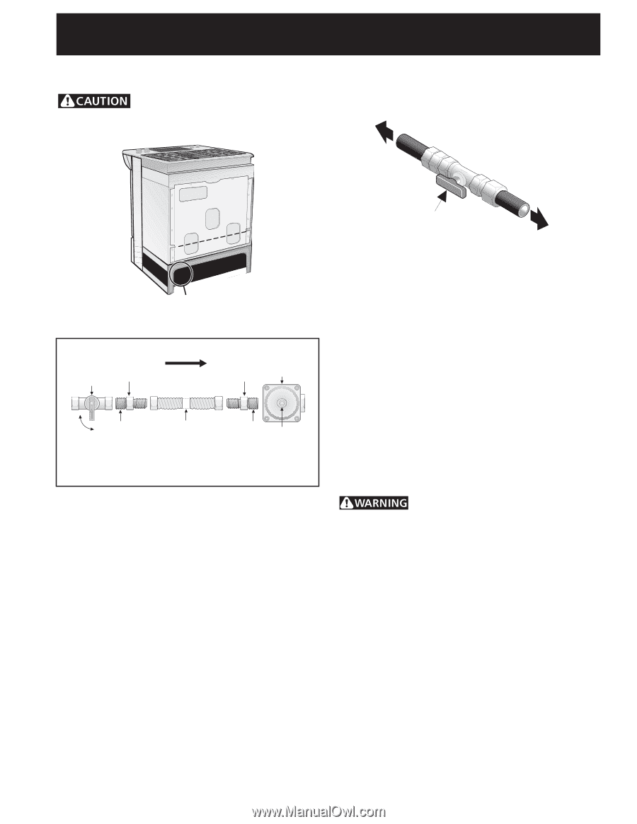
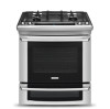
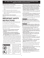
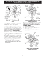
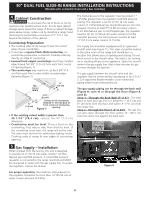
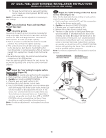
30" DUAL FUEL SLIDE-IN RANGE INSTALLATION INSTRUCTIONS (Models with an Electric Oven and a Gas Cooktop) Connection to Pressure Regulator The regulator is already installed on the appliance. Do not make the connection too tight. The regulator is die cast. Overtightening may crack the regulator resulting in a gas leak and possible fire or explosion. Use pipe-joint compound made for use with Natural and LP/Propane gas to seal all gas connections. If flexible connectors are used, be certain connectors are not kinked. to appliance Shutoff Valve Open position to gas supply line Figure 11 PRESSURE REGULATOR LOCATION Figure 9 Manual Shutoff Valve Flare Union GAS FLOW Pressure Flare Regulator Union On Nipple Off Flexible Connector Nipple Access Cap All connections must be wrench-tightened Figure 10 Assemble the flexible connector from the gas supply pipe to the pressure regulator in the following order: 1. manual shutoff valve (not supplied) 2. 1/2" nipple (not supplied) 3. 1/2" flare union adapter (not supplied) 4. flexible connector (not supplied) 5. 1/2" flare union adapter (not supplied) 6. 1/2" nipple (not supplied) 7. pressure regulator (supplied) The gas supply line to the shutoff valve should be 1/2"(1,27 cm) or 3/4"(1.9 cm) solid pipe. The user must know the location of the main shutoff valve and have easy access to it. When using flexible gas conduit on the range, allow sufficient slack to pull the range outside the cutout for cleaning or servicing. NOTE: Do not allow the flexible conduit to get pinched between the wall and the range. To visually check, remove the range drawer. The supply line must be equipped with an approved manual shutoff valve. This valve should be located in the same room as the range and should be in a location that allows ease of opening and closing. Do not block access to the shutoff valve. The valve is for turning on or shutting off gas to the appliance. Once regulator is in place, open the shutoff valve in the gas supply line. Wait a few minutes for gas to move through the gas line. Leak testing of the appliance shall be conducted according to the manufacturer's instructions. Check for leaks. After connecting the range to the gas supply, check the system for leaks with a manometer. If a manometer is not available, turn on the gas supply and use a liquid leak detector at all joints and connections to check for leaks. Do not use a flame to check for leaks from gas connections. Checking for leaks with a flame may result in a fire or explosion. All openings in the wall or floor where the range is to be installed must be sealed. Tighten all connections if necessary to prevent gas leakage in the cooktop or supply line. Disconnect this range and its individual shutoff valve from the gas supply piping system during any pressure testing of the system at test pressures greater than 1/2 psig (3.5 kPa or 14"(35,56 cm) water column). Isolate the range from the gas supply piping system by closing its individual manual shutoff valve during any pressure testing of the gas supply piping system at test pressures equal to or less than 1/2 psig (3.5 kPa or 14"(35,56 cm) water column). 9
-
 1
1 -
2
-
3
-
 4
4 -
 5
5 -
 6
6 -
 7
7 -
 8
8 -
 9
9 -
 10
10 -
 11
11 -
 12
12 -
 13
13 -
 14
14 -
15
-
16
-
17
-
18
-
19
-
20
-
21
-
22
-
23
-
24
-
25
-
26
-
27
-
28
-
29
-
30
-
31
-
32
-
33
-
34
-
35
-
36
-
37
-
38
-
39
-
40
-
41
-
42
-
43
-
44
 |
 |