Electrolux EIED55HIW Wiring Diagram (All Languages)
Electrolux EIED55HIW - 8.0 cu. Ft. Electric Dryer Manual
 |
UPC - 012505378614
View all Electrolux EIED55HIW manuals
Add to My Manuals
Save this manual to your list of manuals |
Electrolux EIED55HIW manual content summary:
- Electrolux EIED55HIW | Wiring Diagram (All Languages) - Page 1
. Replace Heating element or wiring defective heater and/or wiring and retest. E64 Heater Open Circuit Check heater coils and connections for open circuits. Replace heater and/or Heating element or wiring defective wiring and retest. For Electric Model, check Inlet Thermal Limiter for - Electrolux EIED55HIW | Wiring Diagram (All Languages) - Page 2
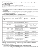
Error Code Interface Board defective wiring problems, replace Electronic Control Control Board faulty Line voltage too low or Electronic Control Board faulty Line seconds. 3. Remove any load from the dryer and press "start pause" to start installation cycle. DIAGNOSTIC MODE 1. Press the "cancel - Electrolux EIED55HIW | Wiring Diagram (All Languages) - Page 3
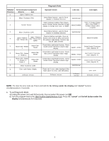
CW + Heater 1 + Heater 2 + Heater 3 Motor CW + Heater Check Motor and Heater function. Check Outlet Control Thermistor value in digit "HEAT3 - NTC1" display. 8 Motor Clockwise (CW) "MOTOR CW" 9 Error code history display Check last 5 error codes displayed (See Table above for error code - Electrolux EIED55HIW | Wiring Diagram (All Languages) - Page 4
touches "cancel (annuler)" et "start (départ)/ pause" pendant 6 secondes pour afficher le dernier code d'erreur enregistré. Le code d'erreur s'affiche à l'écran sous ; Câblage défectueux E63 Élément chauffant Élement chauffant ou câblage à la terre défectueux E64 Élément chauffant Élement - Electrolux EIED55HIW | Wiring Diagram (All Languages) - Page 5
Code d'erreur Anomalie E66 Limiteur thermique avec indication de circuit ouvert la carte d'interface et la carte de contrôle compatible avec la carte d'interface électronique correctes sont installées. Remplacez le matériel approprié. E93 Erreur du total de Chargement des données de Vérifiez - Electrolux EIED55HIW | Wiring Diagram (All Languages) - Page 6
le linge de la sécheuse et appuyez sur "start (départ) / pause" pour lancer le cycle d'installation MODE DIAGNOSTIC 1. Appuyez sur le bouton CANCEL (Annuler) les 5 derniers codes d'erreur codes d'erreur affichés (Voir tableau ci-dessus pour les définitions des codes d'erreur ) Code d'erreur 10 - Electrolux EIED55HIW | Wiring Diagram (All Languages) - Page 7
simultáneamente por 6 segundos para mostrar el último código de error grabado El código de error se mostrará en la pantalla como una E seguida de dos problemas de cableado, cambie la tarjeta de control electrónico y vuelva a probar. E63 Calefactor a tierra Elemento calefactor o cableado Revise - Electrolux EIED55HIW | Wiring Diagram (All Languages) - Page 8
Compruebe si la consola de la tarjeta de interfaz y la tarjeta de control con la tarjeta de interfaz electrónico correctas están instaladas. Cambie el hardware apropiado. Error de Se cargaron datos de configuración E93 comprobación de la equivocados, tarjeta de interfaz o configuración de la - Electrolux EIED55HIW | Wiring Diagram (All Languages) - Page 9
8 Motor en sentido horario "MOTOR CW" 9 Mostrar el historial de Revise los últimos 5 códigos de error mostrados (vea la tabla anterior para lasdefiniciones de códigos de error) Código de error 10 Versión de software Versión de software Versión de software Versión de software NOTA: Para - Electrolux EIED55HIW | Wiring Diagram (All Languages) - Page 10
- Electrolux EIED55HIW | Wiring Diagram (All Languages) - Page 11
- Electrolux EIED55HIW | Wiring Diagram (All Languages) - Page 12
137032700 10
-
 1
1 -
 2
2 -
 3
3 -
 4
4 -
 5
5 -
 6
6 -
 7
7 -
8
-
9
-
10
-
11
-
12
 |
 |
137032700B (0209)
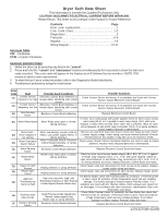
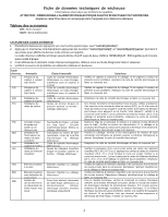
Dryer Tech Data Sheet
This information is intended for Qualified Technicians Only.
CAUTION: DISCONNECT ELECTRICAL CURRENT BEFORE SERVICING
Please Return This Sheet to its Envelope in the Product for Future Reference
Acronym T
able
CW
– Clockwise
CCW
– Counter Clockwise
READING ERROR CODES
1.
Wake the dryer up by pressing any button but “
cancel
”.
2.
Press and hold the
“cancel
”
and
“
start pause
” buttons simultaneously for 6 seconds to show the last error
code recorded.
The error code will appear in the display as an E followed by two numbers. NOTE: E00
means no failure code experienced.
3.
To view the last 5 error codes recorded, refer to the Diagnostic Mode listed below.
4.
Troubleshoot problem by using the chart below.
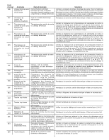
Error
Code
E31
E32
E42
E51
E52
E53
E54
E61
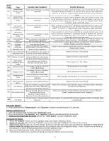
E63
E64
E65
E66
E67
Fault
Contact Sensor
frequency too high
Contact Sensor
frequency too low
Door Sensing
failure
Motor Relay failure
Motor Fault –
motor stopped or
not starting
Motor Centripetal
Switch Failure
Motor Sensing
failure
Heater Relay
failure
Heater to Earth
Ground
Heater Open
Circuit
High Limit
Thermostat trip
count too high
Thermal Limiter
Open Circuit
Heaters Sensing
Failure
Possible Fault Conditions
Electronic Control Board defective or
foreign object interfering with contact
sensor
Electronic Control Board defective or
foreign object interfering with contact
sensor
Electronic Control Board defective
Motor Relay stuck open or closed;
Wiring defective
Motor overheating; Laundry load too
heavy; Low power supply; Motor, or
Wiring defective
Motor Centripetal Switch, Electronic
Control Board Defective, or wiring
defective.
Electronic Control Board defective
Heater relay stuck open or closed;
Wiring defective
Heating element or wiring defective
Heating element or wiring defective
High vent restriction, High Limit
Thermostat defective or Inlet Thermal
Limiter tripped (Electric Model only)
Outlet Thermal Limiter tripped Inlet
Thermal Limiter tripped (Gas
Model only) or wiring defective
Electronic Control Board defective
Possible Solutions
Check Contact Sensor and wiring. If no problems are found with Contact
Sensor, replace Electronic Control Board.
Check Contact Sensor and wiring. If no problems are found with Contact
Sensor, replace Electronic Control Board.
Replace Electronic Control Board.
If motor runs continuously with power applied check for short circuit across
motor relay (RL2), or L1 applied to motor relay output (J3-1) with cycle
stopped. If motor does not start when “start” key is pressed, check for open
circuit between L1 and motor relay connection (J3-2). If no wiring problems
found, replace Electronic Control Board.
Remove any load from dryer and check if drum turns freely by hand. Check
L1 power supply voltage, motor wiring, and motor thermal protector (if motor
thermal protector has tripped, it may take up to 30 minutes to reset).
Check wiring. Check if Motor Centripetal Switches are stuck in open or closed
positions. Replace motor. Replace Electronic Control Board.
Replace Electronic Control Board and retest.
Check for short circuit across heater relay(s) (RL5, RL6, RL7) or L1 applied
to heater relay output(s) (J5-2, J7-1, J7-3)
with cycle stopped. Check for
open circuit between L1 and heater relay connection(s) (J5-1, J5-3, J7-2). If
no wiring problems are found, replace Electronic Control Board and retest.
Check heater coils and connections for short circuits to the cabinet. Replace
heater and/or wiring and retest.
Check heater coils and connections for open circuits. Replace heater and/or
wiring and retest.
For Electric Model, check Inlet Thermal Limiter for continuity.
If Thermal Limiter
is open, check for evidence of high temperature event and any resulting
damage. If no further damage is evident, replace Thermal Limiter. If no
problems are found with the Thermal Limiter, check exhaust vent system for
air blockages. If no problems with vent restrictions, check/replace High Limit
Thermostat, and retest.
Check Outlet Thermal Limiter for continuity. For Gas Model, also check Inlet
Thermal Limiter for continuity.
If Thermal Limiter is open, check for evidence
of high temperature event and any resulting damage. If no further
damage is evident, replace Thermal Limiter and retest.
Replace Electronic Control Board and retest.
Contents
Page
Error code explanation
.............................................
1
Error Code Chart
....................................................
1-2
Diagnostics
.................................................................
3
Français…………………………………………
......
4-6
Español…………………………………………
..............
7-9
Wiring Diagram……………………………………
.......
10-11