Electrolux EL7085ADX Installation Instructions (English, Spanish, French) - Page 11
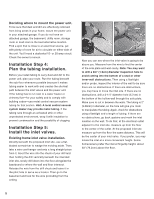
Installation Step 7, Install the power unit.
 |
View all Electrolux EL7085ADX manuals
Add to My Manuals
Save this manual to your list of manuals |
Page 11 highlights
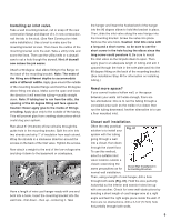
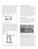
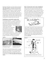
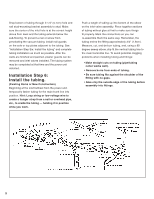
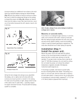
Connect tubing from additional inlet valves to the main trunk line using 90 degree sweep tee elbow fittings. (Fig. 07) and use clamps to hold the sections in place. Be sure to install the sweep tee fittings so the sweep is toward the power unit (Fig. 08). Always run branch lines from the sides or top of the main trunk line, never out of the bottom because this will create a trap for dirt to fall into. Fig. 07 Typical Under-Floor Installation Fig. 08 90 Degree Sweep Tee String the low-voltage wire along as you assemble the tubing. Join or splice low-volt wires with wire connectors at each junction or branch in the tubing. To make sure the polarity is right, always attach wires of the same color to each other - typically copperto-copper and silver-to-silver. Proceed until the tubing system is complete. Hint: Create clamps from extra tubing to hold lowvoltage wire in place. Masonry or concrete walls. If you have to run tubing through masonry or concrete walls, rent a hammer drill and/or masonry hole saw. Run the tubing through and patch the hole once you're up and running. Before drilling, check local building codes for special firewall penetration regulations. The code also should tell you if steel tubing is required. Installation Step 7: Install the power unit. Attach the power unit to the wall with the bottom screws of the mounting bracket located 48" (1.2m) above the floor to allow easy removal of the dirt canister. For proper motor cooling, there must be at least 12" (30.48cm) between the unit and the ceiling. Do not install the power unit where the ambient temperature regularly exceeds 120 degrees Fahrenheit (48.9 degrees C). If mounting on plaster, wall board or panel walls, be sure mounting bolts enter studs. If mounting on a block or concrete wall, drill the holes with a masonry bit and insert plastic or lead anchors. As an alternative to mounting on concrete walls, suspend 2" x 4" (5.1cm x 10.16cm) studs or plywood from overhead. 10
-
 1
1 -
2
-
3
-
4
-
5
-
 6
6 -
 7
7 -
 8
8 -
 9
9 -
 10
10 -
 11
11 -
 12
12 -
 13
13 -
 14
14
 |
 |
