Electrolux RH36WC40GS Complete Owner's Guide (English) - Page 10

Vertical duct-7 Round

Page 10 highlights

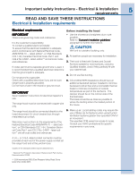
10 Installing the hood Step 6 For rectangular ducted discharge installations only (otherwise skip to next step) Attach exhaust adaptor/damper over knockout opening with two exhaust adaptor screws. Make sure damper pivot is nearest to top/back edge of hood. Remove tape from damper flap. Step 8 Mark holes Select the vent option that your installation will require and proceed to that section: Outside top exhaust (Vertical duct- 3 1/4"x 10" Rectangular) Use the diagram or the hood as a template and mark the locations on the cabinet for ductwork, electrical wiring and keyhole screw slots. Pivot Top/back edge Exhaust transition/damper NOTE: The exhaust adaptor/damper can be installed up to 1 inch on either side of the hood center to accommodate off-center ductwork. In extreme offcenter installations, one end of the duct connector may need to be trimmed to clear the electrical cable clamp. Step 7 For round ducted discharge installations only Hood mounting screws (4) 13 15/16" (30" Hood) 16 15/16" (36" Hood) Cabinet front 13 15/16" (30" Hood) 16 15/16" (36" Hood) Cabinet Bottom 12 9/16"" 5"" 1 1/4"" 5 1/4" 5 1/4" Vertical duct access hole 2" 10 1/2" 1 1/4" Wood shims (recessed bottom cabinets only) Center line Electrical access hole (in cabinet bottom) Outside top exhaust (Vertical duct-7" Round) Use the diagram or the hood as a template and mark the locations on the cabinet for ductwork, electrical wiring and keyhole screw slots. Re-install the round transition with its screws. 7" Round Transition NOTE: The round transition can be installed up to 1 inch on either side of the hood center to accommodate off-center ductwork. In extreme offcenter installations, one end of the duct connector may need to be trimmed to clear the electrical cable clamp. Hood mounting screws (4) 13 15/16" (30" Hood) 16 15/16" (36" Hood) Cabinet front 13 15/16" (30" Hood) 16 15/16" (36" Hood) Cabinet Bottom 12 1/2"" Access hole for 7" round duct 8" DIA. HOLE 5" 2 1/4" 10 1/2" 1 1/2" Wood shims (recessed bottom cabinets only) Center line Electrical access hole (in cabinet bottom)

  • 1
  • 2
  • 3
  • 4
  • 5
  • 6
  • 7
  • 8
  • 9
  • 10
  • 11
  • 12
  • 13
  • 14
  • 15
  • 16
  • 17
  • 18
  • 19

10
10
10
10
10
Step 6
Step 6
Step 6
Step 6
Step 6
For r
For r
For r
For r
For rectangular ducted discharge installations only
ectangular ducted discharge installations only
(otherwise skip to next step)
Attach exhaust adaptor/damper
Attach exhaust adaptor/damper over knockout
opening with two exhaust adaptor screws. Make
sure
damper pivot
pivot
pivot
pivot
pivot is nearest to top/back edge
top/back edge
top/back edge
top/back edge
top/back edge of hood.
Remove tape
tape
tape
tape
tape from damper flap.
ÌÂÍ»¶¼¾
¾º»·¼½¾½µ·Î¸»ÊËź
Ͻĵ¾
¹µËÎлÈÑ
ŸÇÅ
NOTE:
NOTE:
NOTE:
NOTE:
NOTE: The exhaust adaptor/damper can be installed
up to 1 inch on either side of the hood center to
accommodate off-center ductwork. In extreme off-
center installations, one end of the duct connector
may need to be trimmed to clear the electrical cable
clamp.
Step 7
Step 7
Step 7
Step 7
Step 7
For r
For r
For r
For r
For round ducted discharge installations only
ound ducted discharge installations only
Re-install the round transition
ound transition
ound transition
ound transition
ound transition with its screws.
±²³´µ¶·¸
¹º»·¼½¾½µ·
NOTE:
NOTE:
NOTE:
NOTE:
NOTE: The round transition can be installed up to 1
inch on either side of the hood center to
accommodate off-center ductwork. In extreme off-
center installations, one end of the duct connector
may need to be trimmed to clear the electrical cable
clamp.
Step 8
Step 8
Step 8
Step 8
Step 8
Mark holes
Mark holes
Mark holes
Mark holes
Mark holes
Select the vent option that your installation will
require and proceed to that section:
Outside top exhaust
Outside top exhaust
Outside top exhaust
Outside top exhaust
Outside top exhaust
(Vertical duct– 3 1/4”x 10” Rectangular)
Use the diagram or the hood as a template and mark
the locations on the cabinet for ductwork, electrical
wiring and keyhole screw slots.
ÄÀÀ½ÅÆÀ¸¶´¼¶·Å¾³º²Ç¾ÅÈÉÊ
ÂÅÂËÉÌ
²
Ͳ¶´²º
¹¼¶²
ι²³´º¼³µ¹Åµ³³²¾¾Å¿À¹²
ȼ¶Å³µÏ¼¶²´ÅÏÀ´´ÀÆÊ
ÐÀÀ½Å¾¿¼Æ¾ÅȺ²³²¾¾²½
ÏÀ´´ÀÆųµÏ¼¶²´¾ÅÀ¶¹ÑÊ
Ò²º´¼³µ¹Å½¸³´
µ³³²¾¾Å¿À¹²
ÂÓÅÂÔËÂÕÌÅÈÓÖÌÅÄÀÀ½Ê
ÂÕÅÂÔËÂÕÌÅÈÓÕÌÅÄÀÀ½Ê
ÂÓÅÂÔËÂÕÌÅÈÓÖÌÅÄÀÀ½Ê
ÂÕÅÂÔËÂÕÌÅÈÓÕÌÅÄÀÀ½Ê
͵ϼ¶²´Å׺À¶´
ÂÖÅÂËÃÌ
ι²³´º¼³µ¹Åµ³³²¾¾Å¿À¹²
ȼ¶Å³µÏ¼¶²´ÅÏÀ´´ÀÆÊ
ÔÌ
ÂÅÂËÉÌ
͵ϼ¶²´ÅØÀ´´ÀÆ
ÂÃÅÙËÂÕÌ
ÔÅÂËÉÌ
ÔÅÂËÉÌ
ÃÌ
Outside top exhaust
Outside top exhaust
Outside top exhaust
Outside top exhaust
Outside top exhaust
(Vertical duct–7” Round)
Use the diagram or the hood as a template and
mark the locations on the cabinet for ductwork,
electrical wiring and keyhole screw slots.
ÄÀÀ½ÅÆÀ¸¶´¼¶·Å¾³º²Ç¾ÅÈÉÊ
ÂÅÂËÃÌ
Ͳ¶´²º
¹¼¶²
ι²³´º¼³µ¹Åµ³³²¾¾Å¿À¹²
ȼ¶Å³µÏ¼¶²´ÅÏÀ´´ÀÆÊ
ÐÀÀ½Å¾¿¼Æ¾ÅȺ²³²¾¾²½
ÏÀ´´ÀÆųµÏ¼¶²´¾ÅÀ¶¹ÑÊ
ÂÓÅÂÔËÂÕÌÅÈÓÖÌÅÄÀÀ½Ê
ÂÕÅÂÔËÂÕÌÅÈÓÕÌÅÄÀÀ½Ê
ÂÓÅÂÔËÂÕÌÅÈÓÖÌÅÄÀÀ½Ê
ÂÕÅÂÔËÂÕÌÅÈÓÕÌÅÄÀÀ½Ê
͵ϼ¶²´Å׺À¶´
ÂÖÅÂËÃÌ
ι²³´º¼³µ¹Åµ³³²¾¾Å¿À¹²
ȼ¶Å³µÏ¼¶²´ÅÏÀ´´ÀÆÊ
͵ϼ¶²´ÅØÀ´´ÀÆ
ÂÃÅÂËÃÌ
ÃÅÂËÉÌ
ÚÌÅÛÜÝÞ
ÄßàÎ
ÔÌ
ݳ³²¾¾
¿À¹²Å×ÀºÅáÌ
ºÀ¸¶½Å½¸³´
Installing the hood