Epic Fitness E 950 Elliptical English Manual - Page 4
Assembly
 |
View all Epic Fitness E 950 Elliptical manuals
Add to My Manuals
Save this manual to your list of manuals |
Page 4 highlights
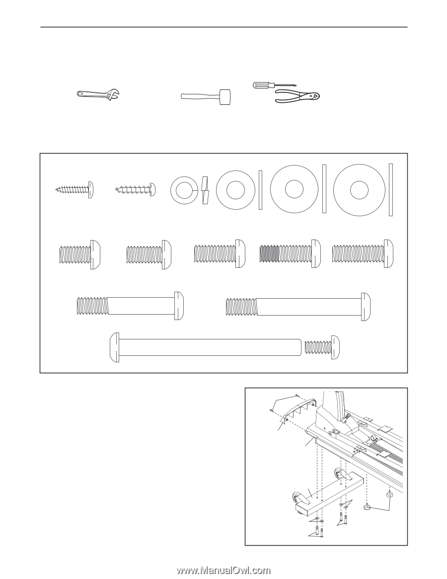
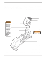
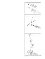
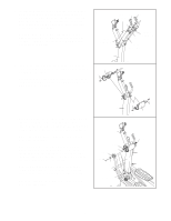
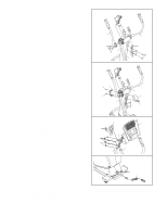
ASSEMBLY To hire an authorized technician to assemble the elliptical exerciser, call toll-free 1-800-445-2480. Assembly requires two persons. Place all parts of the elliptical exerciser in a cleared area and remove the packing materials. Do not dispose of the packing materials until assembly is completed. In addition to the two included hex keys, assembly requires a phillips screwdriver , two adjustable wrenches , a rubber mallet , and pliers . Use the drawings below to identify the small parts used for assembly. The number in parentheses below each drawing is the key number of the part, from the PART LIST on pages 24 and 25. The number following the key number is the quantity needed for assembly. Note: Some small parts may have been preassembled. If a part is not in the parts bag, check to see if it has been preassembled. M4 x 16mm M4 x 16mm Round M8 Split Screw (89)-30 Head Screw (91)-6 Washer (85)-11 M8 x 18mm Washer (93)-4 M8 x 23mm Washer (103)-2 M8 x 25mm Washer (119)-2 M8 x 13mm Button M8 x 16mm Button M8 x 20mm Button M8 x 25mm Patch M8 x 25mm Button Screw (90)-8 Screw (94)-4 Screw (118)-2 Screw (123)-2 Screw (100)-1 M8 x 47mm Button Screw (110)-2 M8 x 65mm Button Screw (95)-8 Union Set (86)-2 1. Orient the Front Stabilizer (3) as shown. Attach the Front Stabilizer to the Frame (1) with four M8 x 65mm Button Screws (95) and four M8 Split Washers (85). 1 91 Next, attach the Front Shield (38) to the Front Stabilizer (3) with two M4 x 16mm Round Head Screws (91). Then, tighten the two Frame Cushions (106) into the underside of the Frame (1). 38 1 3 85 106 85 95 95 4
-
 1
1 -
 2
2 -
 3
3 -
 4
4 -
 5
5 -
 6
6 -
 7
7 -
 8
8 -
 9
9 -
 10
10 -
11
-
12
-
13
-
14
-
15
-
16
-
17
-
18
-
19
-
20
-
21
-
22
-
23
-
24
 |
 |