Epson PowerLite 575W Installation Guide - Page 25
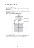
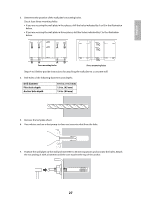
Bolt installation positions, when the projected image is 75 inches or more diagonally.
 |
View all Epson PowerLite 575W manuals
Add to My Manuals
Save this manual to your list of manuals |
Page 25 highlights
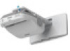
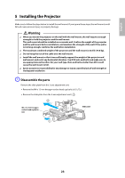
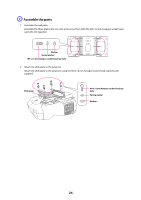
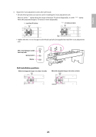
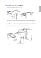
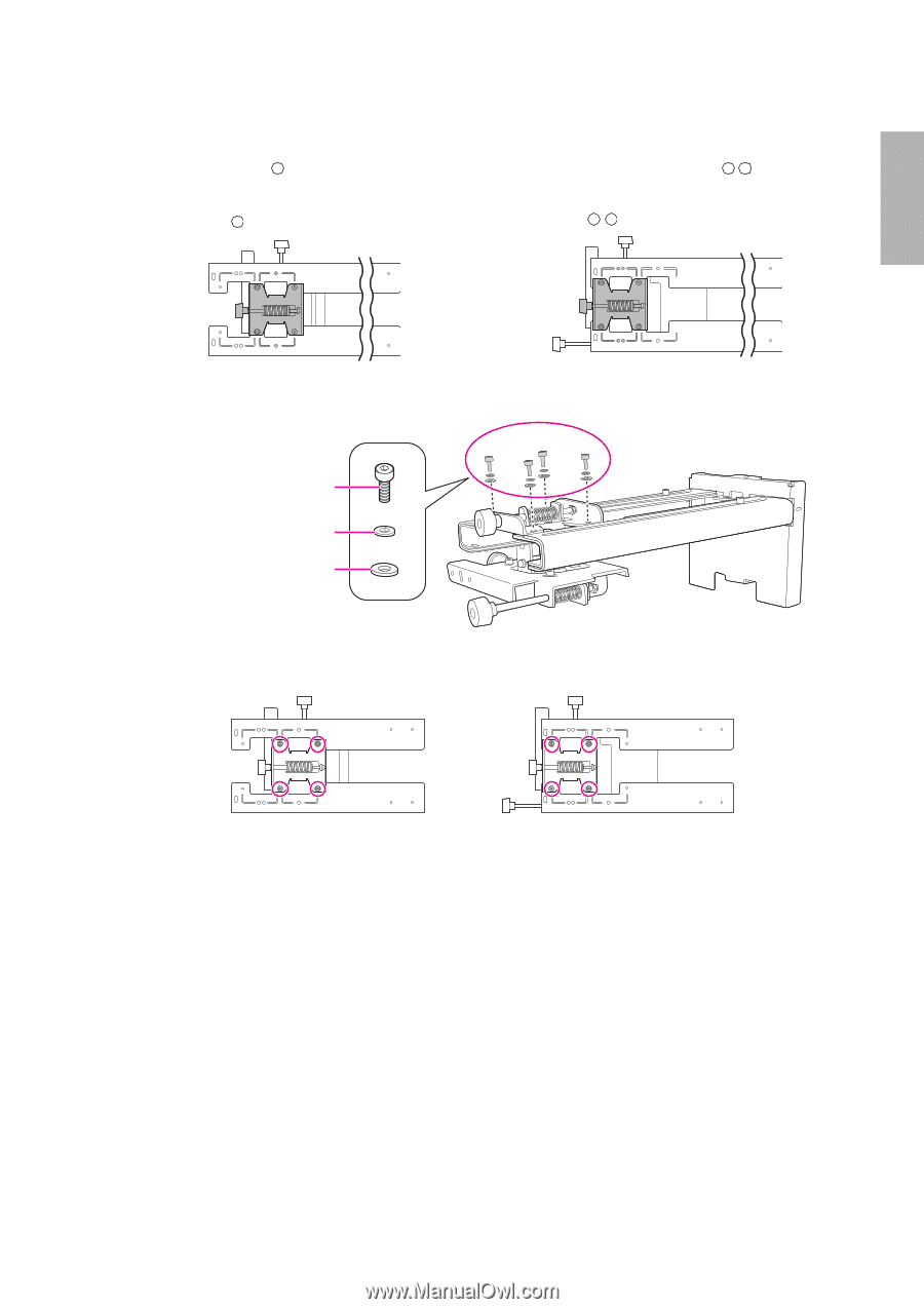
English 3. Attach the 3-axis adjustment unit to the wall mount. • Decide which position you want to use for installing the 3-axis adjustment unit. Mount it at the stamp when the image is less than 75 inches (diagonally), or at the when the projected image is 75 inches or more (diagonally). : Less than 75 inches : 75 inches or more stamp • Tighten the M4 x 12 mm hexagon socket head cap bolts (x4) supplied to install the 3-axis adjustment unit. M4 x 12 mm hexagon socket head cap bolts Spring washer Washer Bolt installation positions When the diagonal image is less than 75 inches When the diagonal image is 75 inches or more 25
-
 1
1 -
2
-
3
-
4
-
5
-
6
-
7
-
8
-
9
-
10
-
11
-
12
-
13
-
14
-
15
-
16
-
17
-
18
-
19
-
 20
20 -
 21
21 -
 22
22 -
 23
23 -
 24
24 -
 25
25 -
 26
26 -
 27
27 -
 28
28 -
 29
29 -
 30
30 -
31
-
32
-
33
-
34
-
35
-
36
-
37
-
38
-
39
-
40
-
41
-
42
-
43
-
44
-
45
-
46
-
47
-
48
-
49
-
50
-
51
-
52
-
53
-
54
-
55
-
56
-
57
-
58
-
59
-
60
-
61
-
62
-
63
-
64
-
65
-
66
-
67
-
68
-
69
-
70
-
71
-
72
-
73
-
74
-
75
-
76
-
77
-
78
-
79
-
80
-
81
-
82
-
83
-
84
-
85
-
86
-
87
-
88
 |
 |
25
English
3.
Attach the 3-axis adjustment unit to the wall mount.
•
Decide which position you want to use for installing the 3-axis adjustment unit.
Mount it at the
stamp when the image is less than 75 inches (diagonally), or at the
stamp
when the projected image is 75 inches or more (diagonally).
•
Tighten the M4 x 12 mm hexagon socket head cap bolts (x4) supplied to install the 3-axis adjustment
unit.
: Less than 75 inches
: 75 inches or more
M4 x 12 mm hexagon socket
head cap bolts
Spring washer
Washer
When the diagonal image is less than 75 inches
When the diagonal image is 75 inches or more
Bolt installation positions