Epson PowerLite 8150i RS-232 Reference Manual (ESC/VP) - Page 3
Serial Communication Specifications - manual
 |
View all Epson PowerLite 8150i manuals
Add to My Manuals
Save this manual to your list of manuals |
Page 3 highlights
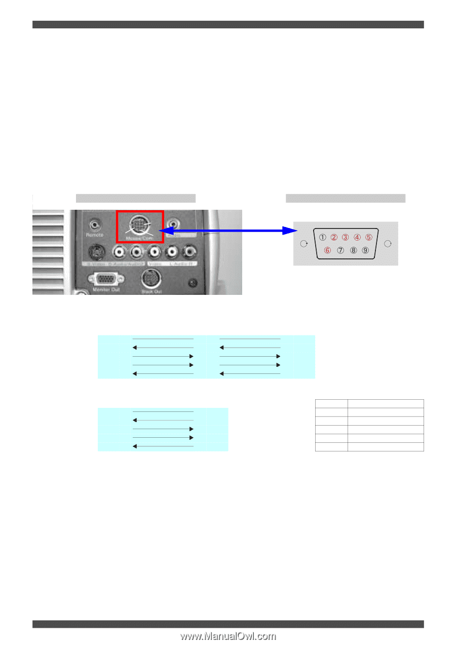
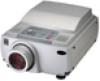
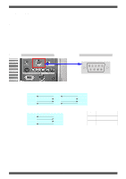
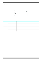
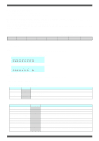
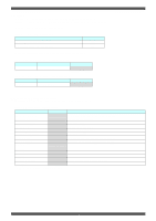
ESC/VP Level 6 Serial Communication Manual (Abridged Edition) 3. SERIAL COMMUNICATION SPECIFICATIONS The projectors can be controlled by connecting a serial cable to the projector (Mouse/Com port) and a computer so that ESC/VP commands can be sent from the computer to the projector. [Communication Conditions] • Communication Speed • Bit length • Parity • Stop bit • Flow control Standard speed: 9600 bps 8 bit None 1 bit Hardware (DTR/DSR) (EMP-8100/9100/8150/7700: 9600 to 57600 bps) (EMP-7600/5600: 9600 to 38400 bps) [Connectors] Connector type: D-sub 9pin (The pins which are actually used are the five pins from 2 to 6. These pins are used to send and receive data, for flow control and for grounding.) Projector PC 8 12 9 13 (RS-232C D-sub 9pin) [Serial cable connection diagram] (Projector) GND 13 RD 9 TD 8 DTR 10 DSR 11 (Main cable) (Projector) GND 5 RD 2 TD 3 DTR 4 DSR 6 (Main cable) (Computer serial cable) 55 5 GND 22 3 TD 33 2 RD 44 6 DSR 66 4 DTR (PC) 5 GND 3 TD 2 RD 6 DSR 4 DTR (PC) List of Signal Function Signal Function GND Ground TD Data transmission RD Data reception DSR Data set ready DTR Data terminal ready 3 of 20
-
 1
1 -
 2
2 -
 3
3 -
 4
4 -
 5
5 -
 6
6 -
 7
7 -
 8
8 -
 9
9 -
10
-
11
-
12
-
13
-
14
-
15
-
16
-
17
-
18
-
19
-
20
 |
 |