Epson Stylus Pro 7600 - Photographic Dye Ink Service Manual - Page 265
P_THICK_0.3/P_THICK Sensor Mounting Plate, Position Adjustment
 |
View all Epson Stylus Pro 7600 - Photographic Dye Ink manuals
Add to My Manuals
Save this manual to your list of manuals |
Page 265 highlights
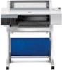
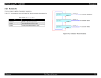
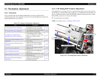
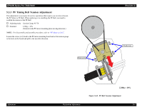
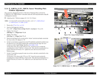
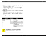
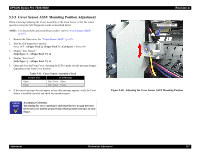
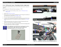
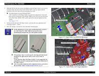
EPSON Stylus Pro 7600/9600 5.3.4 P_THICK_0.3/P_THICK Sensor Mounting Plate Position Adjustment Once you have changed the position of the Sensor Mounting Plate on which the P_THICK_0.3/P_THICK Sensor is mounted, make the following adjustment using the self-diagnostic function. † Adjusting tools: Thickness gauges (0.3, 0.4 / 0.8, 0.9mm) NOTE: For disassembly and assembly procedure, refer to "P_THICK Sensor/ P_THICK Sensor_0.3 ASSY (p.190)". 1. Remove the H Top Cover. (p.165) 2. Start the Self-diagnostic Function: Power OFF → [Paper Feed ∆]+[Paper Feed ∇]+[Cut/Eject] → Power ON 3. Display "Test: Sensor": [SelecType >] → [Paper Feed ∇] x2 4. Display "Sen: Paper": [SelecType >] → [Paper Feed ∇] x2 5. Push down the Paper Set Lever rearward (to "release" position) and make certain that the value on the LCD changes to "10". 6. Set the 0.4-mm thickness gauge between the PF Grid Roller and the Driven Roller near the detection arm on the paper transport path, and bring down the Paper Set Lever toward you (to the "paper holding" position). (See Figure 5-66) At this point, if the value on the LCD is not "01", loosen the screw securing the mounting plate for the P_THICK_0.3 Sensor (left). Then slide the mounting plate to a position where the LCD shows "01", tighten the screw and remove the 0.4-mm thickness gauge. 7. Set the 0.3-mm thickness gauge the same way as above and make certain that the value on the LCD is "00". At this point, if the value on the LCD is not "00", loosen the screw securing the mounting plate for the P_THICK_0.3 Sensor (left). Then slide the mounting plate to a position where the LCD shows "00", tighten the screw and check the previous step again. Revision A From around the sensor, insert the thickness gauge and set the Paper Set Lever in the paper holding position. Driven Roller PF Grid Roller HP side Figure 5-66. Gauge Setting Position Detect arm P_THICK Sensor P_THICK_0.3 Sensor P_THICK Sensor Mounting Plate P_THICK_0.3 Sensor Mounting Plate Figure 5-67. P_THICK Sensor / P_THICK_0.3 Sensor Position Adjustment Adjustment Mechanism Adjustment 265
-
 1
1 -
2
-
3
-
4
-
5
-
6
-
7
-
8
-
9
-
10
-
11
-
12
-
13
-
14
-
15
-
16
-
17
-
18
-
19
-
20
-
21
-
22
-
23
-
24
-
25
-
26
-
27
-
28
-
29
-
30
-
31
-
32
-
33
-
34
-
35
-
36
-
37
-
38
-
39
-
40
-
41
-
42
-
43
-
44
-
45
-
46
-
47
-
48
-
49
-
50
-
51
-
52
-
53
-
54
-
55
-
56
-
57
-
58
-
59
-
60
-
61
-
62
-
63
-
64
-
65
-
66
-
67
-
68
-
69
-
70
-
71
-
72
-
73
-
74
-
75
-
76
-
77
-
78
-
79
-
80
-
81
-
82
-
83
-
84
-
85
-
86
-
87
-
88
-
89
-
90
-
91
-
92
-
93
-
94
-
95
-
96
-
97
-
98
-
99
-
100
-
101
-
102
-
103
-
104
-
105
-
106
-
107
-
108
-
109
-
110
-
111
-
112
-
113
-
114
-
115
-
116
-
117
-
118
-
119
-
120
-
121
-
122
-
123
-
124
-
125
-
126
-
127
-
128
-
129
-
130
-
131
-
132
-
133
-
134
-
135
-
136
-
137
-
138
-
139
-
140
-
141
-
142
-
143
-
144
-
145
-
146
-
147
-
148
-
149
-
150
-
151
-
152
-
153
-
154
-
155
-
156
-
157
-
158
-
159
-
160
-
161
-
162
-
163
-
164
-
165
-
166
-
167
-
168
-
169
-
170
-
171
-
172
-
173
-
174
-
175
-
176
-
177
-
178
-
179
-
180
-
181
-
182
-
183
-
184
-
185
-
186
-
187
-
188
-
189
-
190
-
191
-
192
-
193
-
194
-
195
-
196
-
197
-
198
-
199
-
200
-
201
-
202
-
203
-
204
-
205
-
206
-
207
-
208
-
209
-
210
-
211
-
212
-
213
-
214
-
215
-
216
-
217
-
218
-
219
-
220
-
221
-
222
-
223
-
224
-
225
-
226
-
227
-
228
-
229
-
230
-
231
-
232
-
233
-
234
-
235
-
236
-
237
-
238
-
239
-
240
-
241
-
242
-
243
-
244
-
245
-
246
-
247
-
248
-
249
-
250
-
251
-
252
-
253
-
254
-
255
-
256
-
257
-
258
-
259
-
 260
260 -
 261
261 -
 262
262 -
 263
263 -
 264
264 -
 265
265 -
 266
266 -
 267
267 -
 268
268 -
 269
269 -
 270
270 -
271
-
272
-
273
-
274
-
275
-
276
-
277
-
278
-
279
-
280
-
281
-
282
-
283
-
284
-
285
-
286
-
287
-
288
-
289
-
290
-
291
-
292
-
293
-
294
-
295
-
296
-
297
-
298
-
299
-
300
-
301
-
302
-
303
-
304
-
305
-
306
-
307
-
308
-
309
-
310
-
311
-
312
-
313
-
314
-
315
-
316
-
317
-
318
-
319
-
320
-
321
-
322
-
323
-
324
-
325
-
326
-
327
-
328
-
329
-
330
-
331
-
332
-
333
-
334
-
335
-
336
 |
 |