Epson SureColor S50675 Setup Guide - Page 32
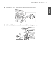
Make sure all four of the mounting screws are loose. To make adjustments, turn the adjustment screw
 |
View all Epson SureColor S50675 manuals
Add to My Manuals
Save this manual to your list of manuals |
Page 32 highlights
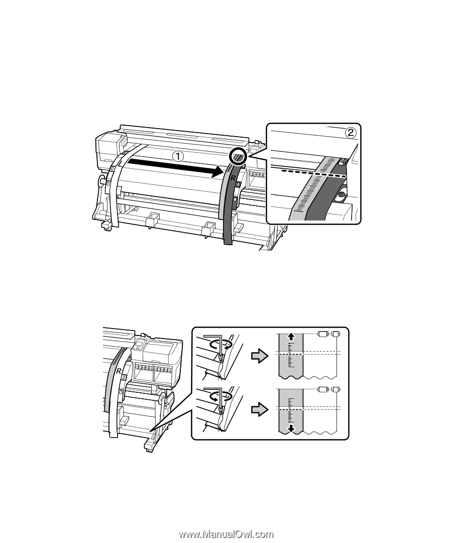
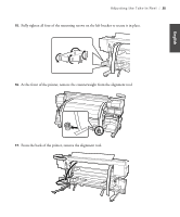
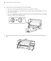
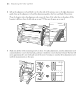
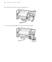
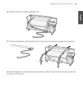
30 | Adjusting the Take-up Reel 6. Lift up the alignment tool and slide it to the other side of the printer, next to the right adjustment guide. Line up the alignment tool and the adjustment guide at the front and back of the printer. Note the location where the alignment tool crosses the front of the white line on the platen. If the location is different from the left side, go to step 7. If they are the same, go to step 8. 7. Make sure all four of the mounting screws are loose. To make adjustments, turn the adjustment screw counterclockwise to move the line back, and turn it clockwise to move the line forward. The line will move approximately 1 mm with each turn of the screw. Continue to turn the silver adjustment screw until the measurements are the same.
-
 1
1 -
2
-
3
-
4
-
5
-
6
-
7
-
8
-
9
-
10
-
11
-
12
-
13
-
14
-
15
-
16
-
17
-
18
-
19
-
20
-
21
-
22
-
23
-
24
-
25
-
26
-
 27
27 -
 28
28 -
 29
29 -
 30
30 -
 31
31 -
 32
32 -
 33
33 -
 34
34 -
 35
35 -
 36
36 -
 37
37 -
38
-
39
-
40
-
41
-
42
-
43
-
44
-
45
-
46
-
47
-
48
-
49
-
50
-
51
-
52
-
53
-
54
-
55
-
56
-
57
-
58
-
59
-
60
-
61
-
62
-
63
-
64
-
65
-
66
-
67
-
68
-
69
-
70
-
71
-
72
-
73
-
74
-
75
-
76
-
77
-
78
-
79
-
80
-
81
-
82
-
83
-
84
-
85
-
86
-
87
-
88
-
89
-
90
-
91
-
92
-
93
-
94
-
95
-
96
-
97
-
98
-
99
-
100
-
101
-
102
-
103
-
104
-
105
-
106
-
107
-
108
-
109
-
110
-
111
-
112
-
113
-
114
-
115
-
116
-
117
-
118
-
119
-
120
-
121
-
122
-
123
-
124
-
125
-
126
-
127
-
128
-
129
-
130
 |
 |