Epson TM U200D Technical Reference - Page 25
Power Supply Connector, Drawer Kick-Out Connector, ESC p, DLE EOT, GS a, Pin assignments - tm u200pd printer
 |
View all Epson TM U200D manuals
Add to My Manuals
Save this manual to your list of manuals |
Page 25 highlights
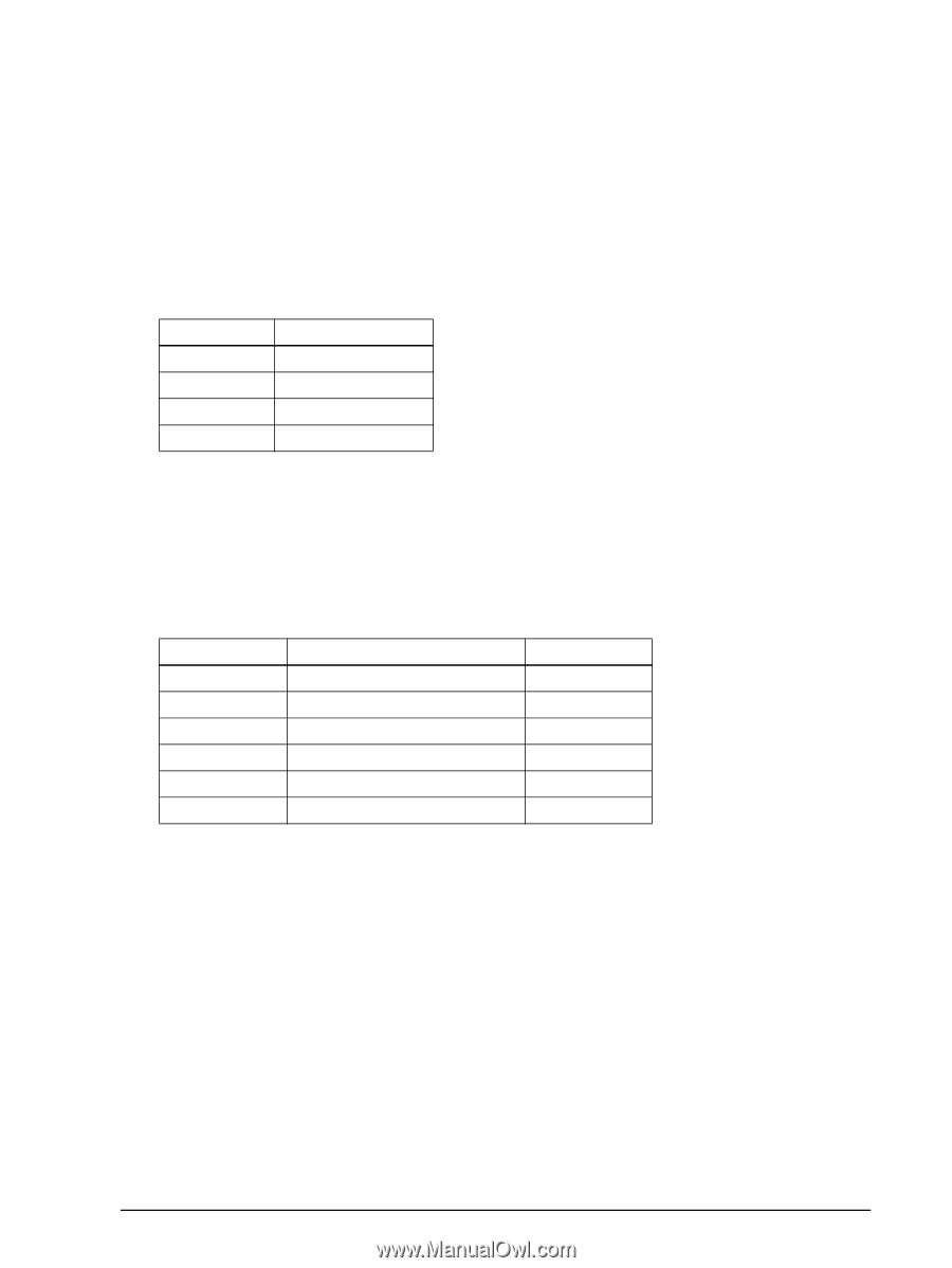
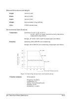
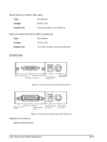
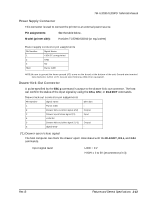
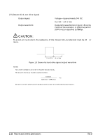
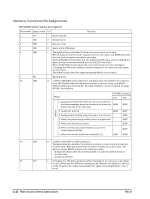
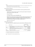
TM-U200D/U200PD Technical Manual Power Supply Connector This connector is used to connect the printer to an external power source. Pin assignments: See the table below. Model (printer side): Hosiden TCS7960-532010 (or equivalent) Power supply connector pin assignments Pin Number Signal Name 1 +30V DC unregulated 2 GND 3 NC Shell Frame GND NOTE: Be sure to ground the frame ground (FG) screw on the board at the bottom of the unit. Ground wire terminal hole diameter: 3.2mm (.13"). Ground wire thickness: AWG 18 or equivalent. Drawer Kick-Out Connector A pulse specified by the ESC p command is output to the drawer kick-out connector. The host can confirm the status of the input signal by using the GS a, GS r, or DLE EOT commands. Drawer kick-out connector pin assignments Pin Number Signal name 1 Frame GND 2 Drawer kick-out drive signal 1(*2) 3 Drawer open/close signal (*1) 4 +24V DC 5 Drawer kick-out drive signal 2 (*2) 6 Signal GND Direction Output Input Output - (*1) Drawer open/close signal The host computer can check the drawer open/close status with the DLE EOT, GS a, and GS r commands. Input signal level: LOW = 0 V HIGH = 2 to 5V (at connector pin 3) Rev. B Features and General Specifications 1-13
-
 1
1 -
2
-
3
-
4
-
5
-
6
-
7
-
8
-
9
-
10
-
11
-
12
-
13
-
14
-
15
-
16
-
17
-
18
-
19
-
 20
20 -
 21
21 -
 22
22 -
 23
23 -
 24
24 -
 25
25 -
 26
26 -
 27
27 -
 28
28 -
 29
29 -
 30
30 -
31
-
32
-
33
-
34
-
35
-
36
-
37
-
38
-
39
-
40
-
41
-
42
-
43
-
44
-
45
-
46
-
47
-
48
-
49
-
50
-
51
-
52
-
53
-
54
-
55
-
56
-
57
-
58
-
59
-
60
-
61
-
62
-
63
-
64
-
65
-
66
-
67
-
68
-
69
-
70
-
71
-
72
-
73
-
74
-
75
-
76
-
77
-
78
-
79
-
80
-
81
-
82
-
83
-
84
-
85
-
86
-
87
-
88
-
89
-
90
-
91
-
92
-
93
-
94
-
95
-
96
-
97
-
98
-
99
-
100
-
101
-
102
-
103
-
104
-
105
-
106
-
107
-
108
-
109
-
110
-
111
-
112
-
113
-
114
-
115
-
116
-
117
-
118
-
119
-
120
-
121
-
122
-
123
-
124
-
125
-
126
-
127
-
128
-
129
-
130
-
131
-
132
-
133
-
134
-
135
-
136
-
137
-
138
-
139
-
140
-
141
-
142
-
143
-
144
-
145
-
146
-
147
-
148
-
149
-
150
-
151
-
152
-
153
-
154
-
155
-
156
-
157
-
158
-
159
-
160
-
161
-
162
-
163
-
164
-
165
-
166
-
167
-
168
-
169
 |
 |