Epson TM-U220 TM-U220 Technical Reference Guide - Page 57
Adjusting the DIP Switches
 |
View all Epson TM-U220 manuals
Add to My Manuals
Save this manual to your list of manuals |
Page 57 highlights
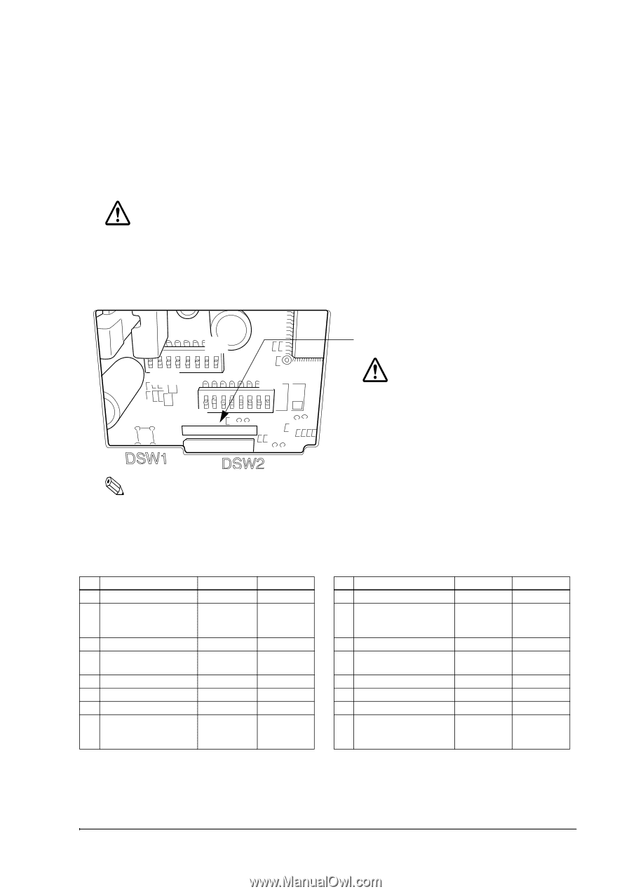
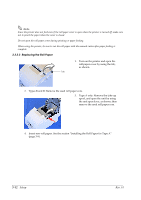
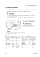
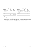
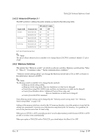
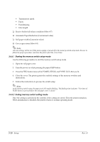
TM-U220 Technical Reference Guide 3.4.2 Adjusting the DIP Switches The printer has two sets of DIP switches. The function of the DIP switches is different for each interface model. If you need to change settings, follow the steps below to make your changes: CAUTION: Turn off the power while removing the DIP switch cover to prevent an electric short, which can damage the printer. Use a crosshead screwdriver to remove the screw holding the DIP switch cover. ON OFF ON OFF Look at the numbers and letters in the area indicated in the illustration.If the last letters are "STD", use the "STD" tables. CAUTION: Be sure to put back the DIP switch cover before using the printer. Note: The functions of the switches are shown in the following sections. 3.4.2.1 When the letters are STD Serial model (DIP Switch 1) SW Function On 1 Data receive error Ignored 2 Receive buffer capacity 40 bytes Off Prints "?" 4 KB 3 Handshaking 4 Word length XON/XOFF 7 bits DTR/DSR 8 bits 5 Parity check 6 Parity selection 7 Transmission speed 8 BUSY condition Yes Even 4800 bps Receive buffer full No Odd 9600 bps Receive buffer full or Offline (DIP Switch 2) SW Function On 1 Print column 42/35 2 Reserved Type A, B (Auto cutter enable/ Fixed to On disable) 3 Reserved - 4 Serial interface selection Memory switch 5 Reserved - 6 Reserved - 7 Pin 6 reset signal Used 8 Pin 25 reset signal Used Off 40/33 Type D Fixed to Off Fixed to Off DIP switch Fixed to Off Fixed to Off Not used Not used Rev. H Setup 3-15
-
 1
1 -
2
-
3
-
4
-
5
-
6
-
7
-
8
-
9
-
10
-
11
-
12
-
13
-
14
-
15
-
16
-
17
-
18
-
19
-
20
-
21
-
22
-
23
-
24
-
25
-
26
-
27
-
28
-
29
-
30
-
31
-
32
-
33
-
34
-
35
-
36
-
37
-
38
-
39
-
40
-
41
-
42
-
43
-
44
-
45
-
46
-
47
-
48
-
49
-
50
-
51
-
 52
52 -
 53
53 -
 54
54 -
 55
55 -
 56
56 -
 57
57 -
 58
58 -
 59
59 -
 60
60 -
 61
61 -
 62
62 -
63
-
64
-
65
-
66
-
67
-
68
-
69
-
70
-
71
-
72
-
73
-
74
-
75
-
76
-
77
-
78
-
79
-
80
-
81
-
82
-
83
-
84
-
85
-
86
-
87
-
88
-
89
-
90
-
91
-
92
-
93
-
94
-
95
-
96
-
97
-
98
-
99
-
100
-
101
-
102
-
103
-
104
-
105
-
106
-
107
-
108
-
109
-
110
-
111
-
112
-
113
-
114
-
115
-
116
-
117
-
118
-
119
-
120
-
121
-
122
-
123
-
124
-
125
-
126
-
127
-
128
-
129
-
130
-
131
-
132
-
133
-
134
-
135
-
136
-
137
-
138
-
139
-
140
-
141
-
142
-
143
-
144
-
145
-
146
-
147
-
148
-
149
-
150
-
151
-
152
-
153
-
154
 |
 |