Fluke 1520 FE 1520 Users Manual
Fluke 1520 Manual
 |
View all Fluke 1520 manuals
Add to My Manuals
Save this manual to your list of manuals |
Fluke 1520 manual content summary:
- Fluke 1520 | FE 1520 Users Manual - Page 1
® 1520 MegOhmMeter Users Manual September 2000 Rev.2, 2/03 © 2000-2003 Fluke Corporation. All rights reserved. Printed in USA All product names are trademarks of their respective companies. - Fluke 1520 | FE 1520 Users Manual - Page 2
- Fluke 1520 | FE 1520 Users Manual - Page 3
Measuring Voltage 18 Checking the Battery 19 Maintaining the Meter 20 Cleaning...20 Replacing and Disposing of the Batteries 21 Testing and Replacing the Fuse 24 Replacement Parts and Optional Accessories 27 Principle of Measurement for Resistance 28 Service Centers 28 Specifications...29 i - Fluke 1520 | FE 1520 Users Manual - Page 4
ii - Fluke 1520 | FE 1520 Users Manual - Page 5
of Tables Table Title Page 1. Key and Switch Descriptions 6 2. Display Description 8 List of Figures Figure Title Page 1. Shipment Content 2 2. Display ...9 3. Connecting to the Circuit Under Test 11 4. Display Example 19 5. Replacing the Batteries 23 6. Replacing the Fuse 26 ii - Fluke 1520 | FE 1520 Users Manual - Page 6
Fluke 1520 Unpacking the Meter The Fluke Model 1520 MegOhmMeter (hereafter, "the meter") is a handheld instrument designed primarily to make resistance/insulation resistance measurements. The MegOhmMeter includes the following items, see Figure 1: • 2 test leads, red and black, 1.5 m • 2 test probes - Fluke 1520 | FE 1520 Users Manual - Page 7
Fluke 1520 Users Manual Figure 1. Shipment Content acf02f.eps 2 - Fluke 1520 | FE 1520 Users Manual - Page 8
and actions that pose hazard(s) to the user. International symbols on the Meter and in the manual are explained below. Y Risk of electric shock J Earth W See manual I Fuse T Equipment protected by double or reinforced Insulation D AC or DC M Battery Recycling information P CAT - Fluke 1520 | FE 1520 Users Manual - Page 9
information carefully before using or servicing the instrument. To avoid electric shock or fire, do the following: • Avoid working alone. • Inspect the test leads for damaged insulation or exposed metal. Check test lead continuity. Damaged leads must be replaced. Do not use the Meter if it looks - Fluke 1520 | FE 1520 Users Manual - Page 10
use the Meter with any parts or cover removed. • Do not use the Meter around explosive gas, vapor or dust. • Disconnect the test leads from power sources and from the Meter before changing the batteries or fuse. • Do not use the Meter in a wet environment. • Use only Fluke specified test leads - Fluke 1520 | FE 1520 Users Manual - Page 11
Fluke 1520 Users Manual Key functions Table 1. Key and Switch Descriptions T L Rotary switch To select a measurement function. Used for the Insulation Resistance and Low Resistance test functions. Press and hold this button until the main reading is stable. Locks the test in Insulation - Fluke 1520 | FE 1520 Users Manual - Page 12
N Z C MegOhmMeter Key functions Table 1 (continued) Resistance Beeper function Turns the Beeper function ON and OFF. When ON, the R icon appears on the display and the Meter beeps at short circuit. Low Resistance function X Turns the test lead resistance compensation ON. The icon appears on the - Fluke 1520 | FE 1520 Users Manual - Page 13
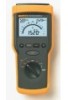
Fluke 1520 Users Manual Display Table 2 and Figure 2 describe the display. Table 2. Display Description 1 Voltage applied to the probes in Insulation Resistance function. 2 Low Resistance/Resistance function indicator. 3 Resistance reading held from the last measurement in Insulation Resistance or - Fluke 1520 | FE 1520 Users Manual - Page 14
1 2 3 10 9 8 7 6 Figure 2. Display MegOhmMeter Key functions 4 5 acf12f.eps 9 - Fluke 1520 | FE 1520 Users Manual - Page 15
Fluke 1520 Users Manual Using the Meter Connecting to the Circuit Under Test W Figure 3 shows the proper connections. Warning To prevent electric shock when performing resistance tests, remove all W power from the circuit to be measured. Warning To prevent electric shock, first connect the test - Fluke 1520 | FE 1520 Users Manual - Page 16
MegOhmMeter Using the Meter Figure 3. Connecting to the Circuit Under Test acf04f.eps 11 - Fluke 1520 | FE 1520 Users Manual - Page 17
Fluke 1520 Users Manual Auto-Shut-Off The Meter automatically turns off after 15 minutes of non-use. In Lo Ohms mode, the meter turns off after 5 minutes of non-use. To turn the meter back on, turn the rotary switch to OFF, then to the desired function. W Measuring Insulation Resistance Warning - Fluke 1520 | FE 1520 Users Manual - Page 18
MegOhmMeter Using the Meter To measure insulation resistance, do the following: 1. Select the test voltage. 2. Connect the probes to the circuit to be measured. The meter automatically detects if the circuit is energized, W and displays the detected voltage. Warning A repetitive beep and the - Fluke 1520 | FE 1520 Users Manual - Page 19
Fluke 1520 Users Manual The Meter beeps when the reading is stable. The upper right display shows the same resistance reading as the main display. When resistance is higher than the maximum display range, the meter test points, release the TEST button. The circuit now discharges through the Meter, - Fluke 1520 | FE 1520 Users Manual - Page 20
MegOhmMeter Using the Meter Using the LOCK Function to Measure Insulation Resistance The LOCK function holds the test voltage on the probes. Use LOCK to make long duration measurements without having to push and hold the TEST button. To use the LOCK function: 1. Press the TEST button, then press - Fluke 1520 | FE 1520 Users Manual - Page 21
Fluke 1520 Users Manual Measuring Low Resistance To measure low resistance: 1. Zero out the test lead resistance (see Table 1). 2. Connect the probes to the circuit to be measured. W If voltage is present on the probes, the voltage is displayed. Warning A repetitive beep - Fluke 1520 | FE 1520 Users Manual - Page 22
MegOhmMeter Using the Meter 5. Exchange the red (+) and black (-) probes on the circuit and repeat steps 3 and 4 to reverse the polarity of the test current. The reading should be the same as the previous. This test is useful to detect corroded connections, which can cause different readings for - Fluke 1520 | FE 1520 Users Manual - Page 23
Fluke 1520 Users Manual Measuring Resistance 1. Connect the probes to the circuit to be measured. Measure voltage first to ensure that no hazardous voltage is present, then switch to Ohms. 2. If the resistance is approximately 30 Ω or less, the Meter beeps. To turn off the beeper, press the beeper - Fluke 1520 | FE 1520 Users Manual - Page 24
Checking the Battery This function tests the battery under simulated load per EN61557. Disconnect all test leads from any circuit. MegOhmMeter Using the Meter Full Empty acf09f.eps 100% - Full 0% - Empty Figure 4. Display Example acf13f.eps 19 - Fluke 1520 | FE 1520 Users Manual - Page 25
Fluke 1520 Users Manual Maintaining the Meter This section provides basic maintenance information, including fuse and battery replacement instructions. Caution Do not attempt to repair or service your Meter unless you are qualified to do so and have the relevant calibration, performance test, and - Fluke 1520 | FE 1520 Users Manual - Page 26
handler. Contact your authorized Fluke Service center for recycling information. The Meter uses four alkaline C cell batteries (supplied). To replace the batteries, do the following (see Figure 5): 1. Turn the rotary switch to the OFF position. 2. Disconnect test leads from any power source - Fluke 1520 | FE 1520 Users Manual - Page 27
Fluke 1520 Users Manual 4. Place the Meter face down on a nonabrasive surface and loosen the two screws with a flat-blade screwdriver. 5. Lift the battery access lid away from the Meter. 6. Replace the C cells as shown in Figure 5. Observe the battery polarity shown in the battery compartment. 7. - Fluke 1520 | FE 1520 Users Manual - Page 28
MegOhmMeter Maintaining the Meter Figure 5. Replacing the Batteries. acf10f.eps 23 - Fluke 1520 | FE 1520 Users Manual - Page 29
1520 Users Manual W Testing and Replacing the Fuse Warning To avoid electric shock, disconnect the test leads from the inputs before opening the Meter for fuse replacement. To prevent personal injury or damage to the Meter, install ONLY Fluke specified fuse identified in the "Replacement Parts - Fluke 1520 | FE 1520 Users Manual - Page 30
MegOhmMeter Maintaining the Meter Replacing the Fuse W Warning To avoid electric shock, personal injury or damage to the Meter, use ONLY the specified fuse, and in accordance with the following procedure. If the previous fuse test indicates that the fuse is defective (resistance > 40 Ω), replace - Fluke 1520 | FE 1520 Users Manual - Page 31
Fluke 1520 Users Manual Figure 6. Replacing the Fuse acf11f.eps 26 - Fluke 1520 | FE 1520 Users Manual - Page 32
MegOhmMeter Replacement Parts and Optional Accessories Replacement Parts and Optional Accessories Replacement Part Battery 1.5 V Alkaline Size C Test Lead set Test Probe, 1 kV, lantern tip, red Test WTool Pack For safety, use exact replacement only. Part Number 423582 669058 803459 803467 - Fluke 1520 | FE 1520 Users Manual - Page 33
Fluke 1520 Users Manual Principle of Measurement for Resistance The Meter measures resistance by inducing a current in the circuit under test, measuring the resultant potential across the circuit, and then calculating the resistance of the circuit. The resistance is then established by performing - Fluke 1520 | FE 1520 Users Manual - Page 34
MegOhmMeter Specifications Specifications Environmental Operating Temperature Storage Temperature Temperature Coefficient Relative Humidity: Non condensing (< 10 °C) 90 % RH (10 °C to 30 °C) 75 % RH (30 °C to 40 °C) 45 % RH (40 °C to 50 °C)(Without Condensation) Dust/water resistance Operating - Fluke 1520 | FE 1520 Users Manual - Page 35
Fluke 1520 Users Manual Size Weight Drop requirement Shock and Vibration Electrical Safety Maximum Operating Voltage Protection Levels Immunity & Emmissions ESD Mechanical Specifications 23,4 x 10 x 6,4 cm (9.2 x 3.9 x 2.5 in) 1 kg (2.2 lbs.) Per IEC 1010-1 Conforms to MIL-PREF-28800F class 3 & 4 - Fluke 1520 | FE 1520 Users Manual - Page 36
MegOhmMeter Specifications Electrical Specifications Battery C Size 1.5 V alkaline, ANSI/NEDA-14A, IECLR14 (4 pieces) Fuse 6 mm x 32 mm (0.25 x 1.25 inch), 0.5 A 660 V, Fast Acting, 50 A Minimum Interrupt rating Insulation Resistance Display Ranges Measurement Range (per EN61557-2) Resolution - Fluke 1520 | FE 1520 Users Manual - Page 37
Fluke 1520 Users Manual Test Voltages Accuracy Nominal Current Number of measurements Circuitry Protection Display Range Measurement Range Accuracy Resolution Analog Bar Graph Open Circuit Voltage Short Circuit Current Test Leads Zero Number of measurements Circuitry Protection 32 250 V, 500 V, - Fluke 1520 | FE 1520 Users Manual - Page 38
Range Resolution Accuracy Analog Bar Graph Range Accuracy Resolution Analog Bar Graph Beeper Voltage 600 V, dc, 50/60 Hz 1 V 2 % + 2 counts 0 to 1000 V Resistance 4000 Ω 2 % + 2 counts 1 Ω 0 to 10 kΩ On at ≈30 Ω or less MegOhmMeter Specifications 33 - Fluke 1520 | FE 1520 Users Manual - Page 39
Fluke 1520 Users Manual Limited Warranty & Limitation of Liability Each Fluke product is warranted to be free from defects in material and workmanship under normal use and service. The warranty period is three years and begins on the date of shipment. Parts, product repairs and services are - Fluke 1520 | FE 1520 Users Manual - Page 40
MegOhmMeter Specifications the Buyer transportation prepaid and the Buyer will be billed for BUT NOT LIMITED TO ANY IMPLIED WARRANTY OF MERCHANTABILITY OR FITNESS FOR A PARTICULAR PURPOSE. FLUKE SHALL NOT BE LIABLE FOR ANY SPECIAL, INDIRECT, INCIDENTAL OR CONSEQUENTIAL DAMAGES OR LOSSES, INCLUDING - Fluke 1520 | FE 1520 Users Manual - Page 41
Fluke 1520 Users Manual 36
-
 1
1 -
 2
2 -
 3
3 -
 4
4 -
 5
5 -
 6
6 -
 7
7 -
8
-
9
-
10
-
11
-
12
-
13
-
14
-
15
-
16
-
17
-
18
-
19
-
20
-
21
-
22
-
23
-
24
-
25
-
26
-
27
-
28
-
29
-
30
-
31
-
32
-
33
-
34
-
35
-
36
-
37
-
38
-
39
-
40
-
41
 |
 |

September 2000 Rev.2, 2/03
© 2000-2003
Fluke Corporation. All rights reserved. Printed in USA
All product names are trademarks of their respective companies.
®
1520
MegOhmMeter
Users Manual