Fluke 279FC User Manual - Page 27
Basic Measurements, AC and DC Voltage Measurements
 |
View all Fluke 279FC manuals
Add to My Manuals
Save this manual to your list of manuals |
Page 27 highlights
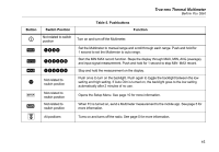
Basic Measurements XW Warning To prevent possible electrical shock, fire, or personal injury, disconnect power and discharge all high-voltage capacitors before you measure resistance, continuity, capacitance, or a diode junction. This section is about how to make basic measurements with the Multimeter. When you connect the test leads to the circuit or device, always: • Connect the common (COM) test lead before the live lead. • Remove the live test lead before the common test lead. True-rms Thermal Multimeter Basic Measurements Basic measurements and tests: • AC and DC Voltage Measurements. See Figure 4. • Volts/Hertz Ratio. See Figure 6. • Resistance Measurements. See Figure 7. • Capacitance Measurements. See Figure 8. • Continuity Test. See Figure 9. • AC Current Measurements. See Figure 10. • Diode Test. See Figure 11. • Frequency Measurements. See Figure 12. AC and DC Voltage Measurements To set the dc or ac range: 1. Turn the rotary dial to . See Figure 4. 2. Push to toggle the voltage between millivolts dc and millivolts ac. 3. Push to scroll through each range. 17
-
 1
1 -
2
-
3
-
4
-
5
-
6
-
7
-
8
-
9
-
10
-
11
-
12
-
13
-
14
-
15
-
16
-
17
-
18
-
19
-
20
-
21
-
 22
22 -
 23
23 -
 24
24 -
 25
25 -
 26
26 -
 27
27 -
 28
28 -
 29
29 -
 30
30 -
 31
31 -
 32
32 -
33
-
34
-
35
-
36
-
37
-
38
-
39
-
40
-
41
-
42
-
43
-
44
-
45
-
46
-
47
-
48
-
49
-
50
-
51
-
52
-
53
-
54
 |
 |
