Fluke 28IIEX Fluke 28IIEx User Manual - Page 28
Zero Input Behavior of True-rms Meters, Low-Pass Filter, AC current: below 3 % of 600
 |
View all Fluke 28IIEX manuals
Add to My Manuals
Save this manual to your list of manuals |
Page 28 highlights
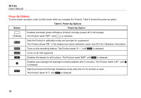
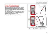
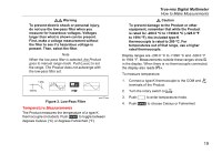
28 II Ex Users Manual When you measure voltage, the Product puts approximately 10-MΩ (10,000,000 Ω) impedance in parallel with the circuit. This loading effect can cause measurement errors in high-impedance circuits. In most cases, the error is negligible (0.1 % or less) if the circuit impedance is 10 kΩ (10,000 Ω) or less. For better accuracy when you measure the dc offset of an ac voltage, measure the ac voltage first. Record the ac voltage range, then manually select a dc voltage range equal to or higher than the ac range. This procedure has better accuracy of the dc measurement because the input protection circuits are disabled. Zero Input Behavior of True-rms Meters True-rms meters accurately measure distorted waveforms, but when the input leads are shorted together in the ac functions, the Product shows a measurement between 1 and 30 counts. When the test leads are open, the measurements can change from interference. These offset measurements are common. They do not change the ac measurement accuracy of the Product for the specified measurement ranges. Unspecified input levels are: • AC voltage: below 3 % of 600 mV ac, or 18 mV ac • AC current: below 3 % of 60 mA ac, or 1.8 mA ac • AC current: below 3 % of 600 μA ac, or 18 μA ac 18 Low-Pass Filter The Product is has an ac low-pass filter. When you measure ac voltage or ac frequency, push to set the low-pass filter mode (K). The Product measures in the chosen mode, but the signal diverts through a filter that stops unwanted voltages more than 1 kHz, refer to Figure 3. The lower frequency voltages go through with decreased accuracy to the measurement less than 1 kHz. The low-pass filter can get you better measurement performance on composite sine waves that are typically found on inverters and variable-frequency motor drives.
-
 1
1 -
2
-
3
-
4
-
5
-
6
-
7
-
8
-
9
-
10
-
11
-
12
-
13
-
14
-
15
-
16
-
17
-
18
-
19
-
20
-
21
-
22
-
 23
23 -
 24
24 -
 25
25 -
 26
26 -
 27
27 -
 28
28 -
 29
29 -
 30
30 -
 31
31 -
 32
32 -
 33
33 -
34
-
35
-
36
-
37
-
38
-
39
-
40
-
41
-
42
-
43
-
44
-
45
-
46
-
47
-
48
-
49
-
50
-
51
-
52
-
53
-
54
-
55
-
56
-
57
-
58
-
59
-
60
-
61
-
62
-
63
-
64
 |
 |
