Fluke 28IIEX Fluke 28IIEx User Manual - Page 32
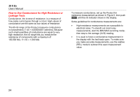
Resistance Measurements, and discharge all high-voltage capacitors
 |
View all Fluke 28IIEX manuals
Add to My Manuals
Save this manual to your list of manuals |
Page 32 highlights
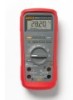
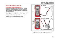
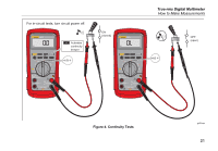
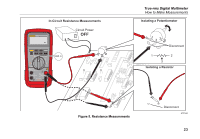
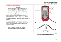
28 II Ex Users Manual Resistance Measurements WCaution To prevent damage to the Product or to the equipment under test, disconnect the power and discharge all high-voltage capacitors before you measure resistance. The Product sends a small current through the circuit to measure resistance. Because this current flows through all possible paths between the probes, the resistance measurement shows the total resistance of all paths between the probes. The resistance ranges of the Product are 600.0 Ω, 6.000 kΩ, 60.00 kΩ, 600.0 kΩ, 6.000 MΩ, and 50.00 MΩ. Connect the Product to the circuit as shown in Figure 5 to measure resistance. Some guidelines for resistance measurements are: • The measured value of a resistor in a circuit can be different than the resistor's rated value. • The test leads can add 0.1 Ω to 0.2 Ω of error to resistance measurements. To test the leads, touch the probe tips together and read the resistance of the leads. If necessary, you can use the relative (REL) mode to automatically subtract this value. • The resistance function can output a voltage sufficient to forward-bias silicon diode or transistor junctions, which can cause them to conduct. If this occurs, push C to apply a lower current in the next higher range. If the value is higher, use the higher value. Refer to the Input Characteristics table in the specifications section for typical short-circuit currents. 22
-
 1
1 -
2
-
3
-
4
-
5
-
6
-
7
-
8
-
9
-
10
-
11
-
12
-
13
-
14
-
15
-
16
-
17
-
18
-
19
-
20
-
21
-
22
-
23
-
24
-
25
-
26
-
 27
27 -
 28
28 -
 29
29 -
 30
30 -
 31
31 -
 32
32 -
 33
33 -
 34
34 -
 35
35 -
 36
36 -
 37
37 -
38
-
39
-
40
-
41
-
42
-
43
-
44
-
45
-
46
-
47
-
48
-
49
-
50
-
51
-
52
-
53
-
54
-
55
-
56
-
57
-
58
-
59
-
60
-
61
-
62
-
63
-
64
 |
 |