Fluke 831 Product Manual - Page 28
Mount components, Mount brackets
 |
View all Fluke 831 manuals
Add to My Manuals
Save this manual to your list of manuals |
Page 28 highlights
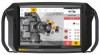
On-board help Mount components Mount brackets Note The system is delivered with fully assembled brackets with both the sensALIGN 3 sensor and the reflector already assembled. In this case, the bracket holding the sensor is mounted on the shaft on the left side of the couplings or the solid coupling hub on the left side (usually stationary machine). The bracket assembly holding the reflector is mounted on the shaft on the right side of the couplings or the solid coupling hub on the right side (usually moveable machine). Mount the brackets on either side of the coupling on either the shafts or on the solid coupling hubs, and both at the same rotational position. Please note the following in order to obtain the highest possible measurement accuracy and to avoid damage to equipment: CAUTION Ensure that the brackets fit solidly onto their mounting surfaces! Do not use self-constructed mounting brackets, or modify the original bracket configuration supplied by Fluke (for example, do not use support posts longer than those supplied with the bracket). l (A) Anchor peg l Choose the shortest support posts which will still allow the laser beam to pass over or through the coupling. Insert the support posts into the bracket.. l Fasten them in place by tightening the hex screws on the sides of the bracket frame. l Place the bracket on the shaft or coupling, wrap the chain around the shaft and feed it through the other side of the bracket: if the shaft is smaller than the width of the bracket frame, insert the chain from the inside of the bracket as shown in the diagram; if the shaft is larger than the bracket width, insert the chain into the frame from the outside. l Catch the chain loosely on the anchor peg (A). l Turn the bracket thumbscrew to tighten the assembly onto the shaft. l Clip the loose end of the chain back onto itself. The bracket should now be tight upon the shaft. Do not push or pull on the bracket to check, since this could loosen its mounting. To remove the brackets, loosen the thumbscrew, then remove the chain from its anchor peg. MyFlukeStore Shop for Fluke products online at: www. .com 1.888.610.7664
-
 1
1 -
2
-
3
-
4
-
5
-
6
-
7
-
8
-
9
-
10
-
11
-
12
-
13
-
14
-
15
-
16
-
17
-
18
-
19
-
20
-
21
-
22
-
 23
23 -
 24
24 -
 25
25 -
 26
26 -
 27
27 -
 28
28 -
 29
29 -
 30
30 -
 31
31 -
 32
32 -
 33
33 -
34
-
35
-
36
-
37
-
38
-
39
-
40
-
41
-
42
-
43
-
44
-
45
-
46
-
47
-
48
-
49
-
50
-
51
-
52
-
53
-
54
-
55
-
56
-
57
-
58
-
59
-
60
-
61
-
62
-
63
-
64
-
65
-
66
-
67
-
68
-
69
-
70
-
71
-
72
-
73
-
74
-
75
-
76
-
77
-
78
-
79
-
80
-
81
-
82
-
83
-
84
-
85
-
86
-
87
-
88
-
89
-
90
-
91
-
92
-
93
-
94
-
95
-
96
-
97
-
98
-
99
-
100
-
101
-
102
-
103
-
104
-
105
-
106
-
107
-
108
-
109
-
110
-
111
-
112
-
113
-
114
-
115
-
116
-
117
-
118
-
119
-
120
-
121
-
122
-
123
 |
 |
