Foxconn A6VMX Multi language Manual - Page 23
Jumpers - motherboard manual
 |
View all Foxconn A6VMX manuals
Add to My Manuals
Save this manual to your list of manuals |
Page 23 highlights
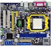
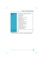
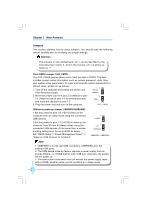
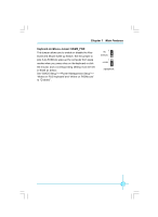
Chapter 1 Main Features Jumpers This section explains how to setup jumpers. You should read the following content carefully prior to modifying any jumper settings. Attention The jumpers on the motherboard, pin 1 can be identified by the bold silkscreen next to it. And in this manual, pin 1 is simply labeled as "1". Clear CMOS Jumper: CLR_CMOS The CLR_CMOS jumper allows you to clear the data in CMOS. The data includes system setup information such as system password, data, time, and system setup parameters. To clear and reset the system parameters to default setup, please do as follows: 1. Turn off the computer and unplug the power cord 1 Normal from the power supply. (default) 2. Move the jumper cap from pins 2-3 (default) to pins 1-2. Keep the cap on pins 1-2 for several seconds, then move the cap back to pins 2-3. 1 Clear 3. Plug the power cord and turn on the computer. CLR_ CMOS USB device wake-up Jumper: USBPWR1/USBPWR2 1.Set the jumper to pins 1-2 (+5V) to wake up the computer from S1 sleep mode using the connected USB devices. 2.Set the jumper to pins 2-3 (+5VSB) to wake up the computer from S3 and S4 sleep modes using the connected USB devices. At the same time, a corresponding setting must be set in BIOS as below: Set "CMOS Setup"=>"Power Management Setup"=> "Wake on USB Devices" to "Enabled". 1 +5VSB 1 +5V (Default) USBPWR1 / USBPWR2 Note 1. USBPW R1 is for the rear USB connectors, USBPW R2 is for the internal USB ports. 2. The USB device wake-up feature requires a power supply that can provide 500mA on +5VSB lead for each USB port; otherwise, the system will not power up. 3. The total current consumed must not exceed the power supply capability (+5VSB) whether under normal condition or in sleep mode. 18
-
 1
1 -
2
-
3
-
4
-
5
-
6
-
7
-
8
-
9
-
10
-
11
-
12
-
13
-
14
-
15
-
16
-
17
-
 18
18 -
 19
19 -
 20
20 -
 21
21 -
 22
22 -
 23
23 -
 24
24 -
 25
25 -
 26
26 -
 27
27 -
 28
28 -
29
-
30
-
31
-
32
-
33
-
34
-
35
-
36
-
37
-
38
-
39
-
40
-
41
-
42
-
43
-
44
 |
 |