Foxconn A75M User manual - Page 21
Fan Connectors, SYS_FAN, CPU_FAN 1, CPU_FAN 2, Speaker Connector : SPEAKER, COM Connector : COM1 - pc
 |
View all Foxconn A75M manuals
Add to My Manuals
Save this manual to your list of manuals |
Page 21 highlights
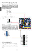
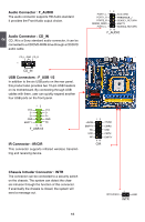
Fan Connectors : SYS_FAN, CPU_FAN 1 CPU_FAN 2 There are three main fan headers on this motherboard. The fan speed can be controlled and monitored in "PC Health Status" section of the BIOS Setup. These fans can be automatically turned off after the system enters S3, S4 and S5 sleeping states. 1 GND POWER SENSE CONTROL CPU_FAN/SYS_FAN 2 Speaker Connector : SPEAKER The speaker connector is used to connect speaker of the chassis. SPKJ 1 EMPTY 2 NC 3 SPKJ 4 SPEAKER COM Connector : COM1 This motherboard supports one serial RS232 COM port for legacy compatibility. User must purchase another RS232 cable with a 9-pin D-sub connector at one end to connect with the external RS232 device and another end with 10-pin female connector to connect with COM1 connector in the motherboard. 12 RLSD SIN SOUT DTR GND DSR RTS CTS RI EMPTY 9 10 COM1 LPT Connector (optional) : LPT The connector supports parallel port which can be connected to a printer or a scanner. System usually assign IRQ7 as it's default interrupt request and the parallel port has three operation mode: [SPP], [EPP], [ECP]. 14 Strobe Data it [0] Data it [1] Data it [2] Data it [3] Data it [4] Data it [5] Data it [6] Data it [7] ACK Busy Paper End Select 12 25 26 LPT Auto Feed Error INIT SLCT IN Ground Ground Ground Ground Ground Ground Ground Ground Empty
-
 1
1 -
2
-
3
-
4
-
5
-
6
-
7
-
8
-
9
-
10
-
11
-
12
-
13
-
14
-
15
-
 16
16 -
 17
17 -
 18
18 -
 19
19 -
 20
20 -
 21
21 -
 22
22 -
 23
23 -
 24
24 -
 25
25 -
 26
26 -
27
-
28
-
29
-
30
-
31
-
32
-
33
-
34
-
35
-
36
-
37
-
38
-
39
-
40
-
41
-
42
-
43
-
44
-
45
-
46
-
47
-
48
-
49
-
50
-
51
-
52
-
53
-
54
-
55
-
56
-
57
-
58
-
59
-
60
-
61
-
62
-
63
-
64
-
65
-
66
-
67
-
68
-
69
-
70
-
71
-
72
-
73
-
74
-
75
-
76
-
77
-
78
-
79
-
80
-
81
-
82
-
83
-
84
-
85
-
86
-
87
-
88
-
89
-
90
-
91
-
92
-
93
-
94
-
95
-
96
-
97
-
98
-
99
-
100
-
101
-
102
-
103
-
104
 |
 |
