Foxconn A75M User manual - Page 22
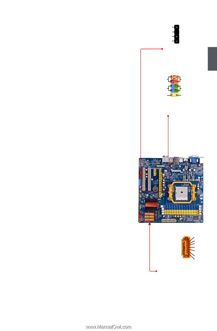
S/PDIF Connector : SPDIF_OUT, Front Panel Connector : FP1, Serial ATA Connectors : SATA1/2/3/4/5/6
 |
View all Foxconn A75M manuals
Add to My Manuals
Save this manual to your list of manuals |
Page 22 highlights
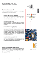
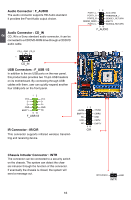
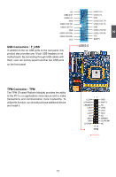
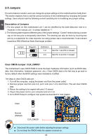
2 S/PDIF Connector : SPDIF_OUT The connector is used for S/PDIF output. Front Panel Connector : FP1 This motherboard includes one connector for connecting the front panel switch and LED Indicators. Hard Disk LED Connector (HDD-LED) Connect to the chassis front panel IDE indicator LED. It indicates the active status of the hard disks. This 2-pin connector is directional with +/- sign. Reset Switch (RESET-SW) Attach the connector to the Reset switch on the front panel of the case; the system will restart when the switch is pressed. Power LED Connector (PWR-LED) Connect to the power LED indicator on the front panel of the chassis. The Power LED indicates the system's status. When the system is in operation (S0 status), the LED is on. When the system gets into sleep mode (S1) , the LED is blinking; When the system is in S3/S4 sleep state or power off mode (S5), the LED is off. This 2-pin connector is directional with +/- sign. Power Switch Connector (PWR-SW) Connect to the power button on the front panel of the chassis. Push this switch allows the system to be turned on and off rather than using the power supply button. Serial ATA Connectors : SATA1/2/3/4/5/6 The Serial ATA connector is used to connect with SATA Hard Disk or CD devices which support this feature. Serial ATA II interface allows up to 300MB/s data transfer rate. (Hundson D3 supports SATA III) +5V 1 EMPTY 2 SPDIF_OUT 3 GND 4 SPDIF_OUT 12 + + HDD-LED - PWR-LED - RESET-SW PWR-SW NC EMPTY 9 10 FP1 1 GND TX+ TXGND RXRX+ GND SATA1/2/3/4/5/6 15
-
 1
1 -
2
-
3
-
4
-
5
-
6
-
7
-
8
-
9
-
10
-
11
-
12
-
13
-
14
-
15
-
16
-
 17
17 -
 18
18 -
 19
19 -
 20
20 -
 21
21 -
 22
22 -
 23
23 -
 24
24 -
 25
25 -
 26
26 -
 27
27 -
28
-
29
-
30
-
31
-
32
-
33
-
34
-
35
-
36
-
37
-
38
-
39
-
40
-
41
-
42
-
43
-
44
-
45
-
46
-
47
-
48
-
49
-
50
-
51
-
52
-
53
-
54
-
55
-
56
-
57
-
58
-
59
-
60
-
61
-
62
-
63
-
64
-
65
-
66
-
67
-
68
-
69
-
70
-
71
-
72
-
73
-
74
-
75
-
76
-
77
-
78
-
79
-
80
-
81
-
82
-
83
-
84
-
85
-
86
-
87
-
88
-
89
-
90
-
91
-
92
-
93
-
94
-
95
-
96
-
97
-
98
-
99
-
100
-
101
-
102
-
103
-
104
 |
 |