Foxconn B75MX-D User manual - Page 24
COM Header : COM2, Chassis Intrusion Alarm Header : INTR, USB 2.0 Headers: F_USB1/2, USB 3.0 Header
 |
View all Foxconn B75MX-D manuals
Add to My Manuals
Save this manual to your list of manuals |
Page 24 highlights
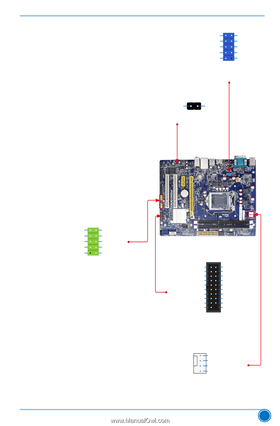
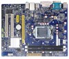
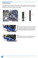
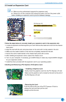
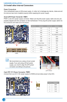
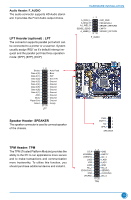
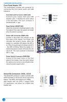
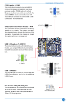
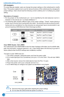
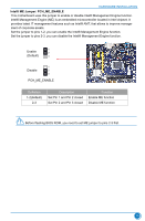
COM Header : COM2 This motherboard supports one serial RS232 COM port for legacy compatibility. User must purchase another RS232 cable with a 9-pin D-sub connector at one end to connect with the external RS232 device and another end with 10-pin female connector to connect with COM1 connector in the motherboard. HARDWARE INSTALLATION DCD SOUT GND RTS RI 12 9 10 SIN DTR DSR CTS EMPTY COM2 Chassis Intrusion Alarm Header : INTR The connector can be connected to a security switch on the chassis. The system can detect the chassis intrusion through the function of this connector. If eventually the chassis is closed, the system will send a message out. INTRUDERJ 1 GND INTR USB 2.0 Headers: F_USB1/2 These connectors comply with USB 2.0 specification, you can get USB ports by connecting the USB module cable to any of these connec- tors. VCC DD+ GND EMPTY 12 9 10 VCC DD+ GND GND F_USB1/2 USB 3.0 Header This connectors are used to connect with the USB3.0 specification, and is for the additional USB3.0 ports. 19 20 NC USB2.0 D+ USB2.0 D- GND USB3.0 SS TX+ USB3.0 SS TX- GND USB3.0 SS RX+ USB3.0 SS RX- VCC USB2.0 D+ USB2.0 DGND USB3.0 SS TX+ USB3.0 SS TXGND USB3.0 SS RX+ USB3.0 SS RXVCC EMPTY 1 2 USB 3.0 Fan Headers: CPU_FAN, SYS_FAN The fan speed can be controlled and monitored in the BIOS Setup. These fans can be automatically turned off after the system enters S3, S4 and S5 sleeping states. 1 GND POWER SENSE CONTROL CPU_FAN/SYS_FAN 17
-
 1
1 -
2
-
3
-
4
-
5
-
6
-
7
-
8
-
9
-
10
-
11
-
12
-
13
-
14
-
15
-
16
-
17
-
18
-
 19
19 -
 20
20 -
 21
21 -
 22
22 -
 23
23 -
 24
24 -
 25
25 -
 26
26 -
 27
27 -
 28
28 -
 29
29 -
30
-
31
-
32
-
33
-
34
-
35
-
36
-
37
-
38
-
39
-
40
-
41
-
42
-
43
-
44
-
45
-
46
-
47
-
48
-
49
-
50
-
51
-
52
-
53
-
54
-
55
-
56
-
57
-
58
-
59
-
60
-
61
-
62
-
63
-
64
-
65
-
66
-
67
-
68
-
69
-
70
-
71
-
72
-
73
 |
 |