Foxconn G31S-K English Manual. - Page 21
USB Connectors : F_USB1/2, Speaker Connector : SPEAKER, S/PDIF OUT Connector : SPDIF_OUT, LPC
 |
View all Foxconn G31S-K manuals
Add to My Manuals
Save this manual to your list of manuals |
Page 21 highlights
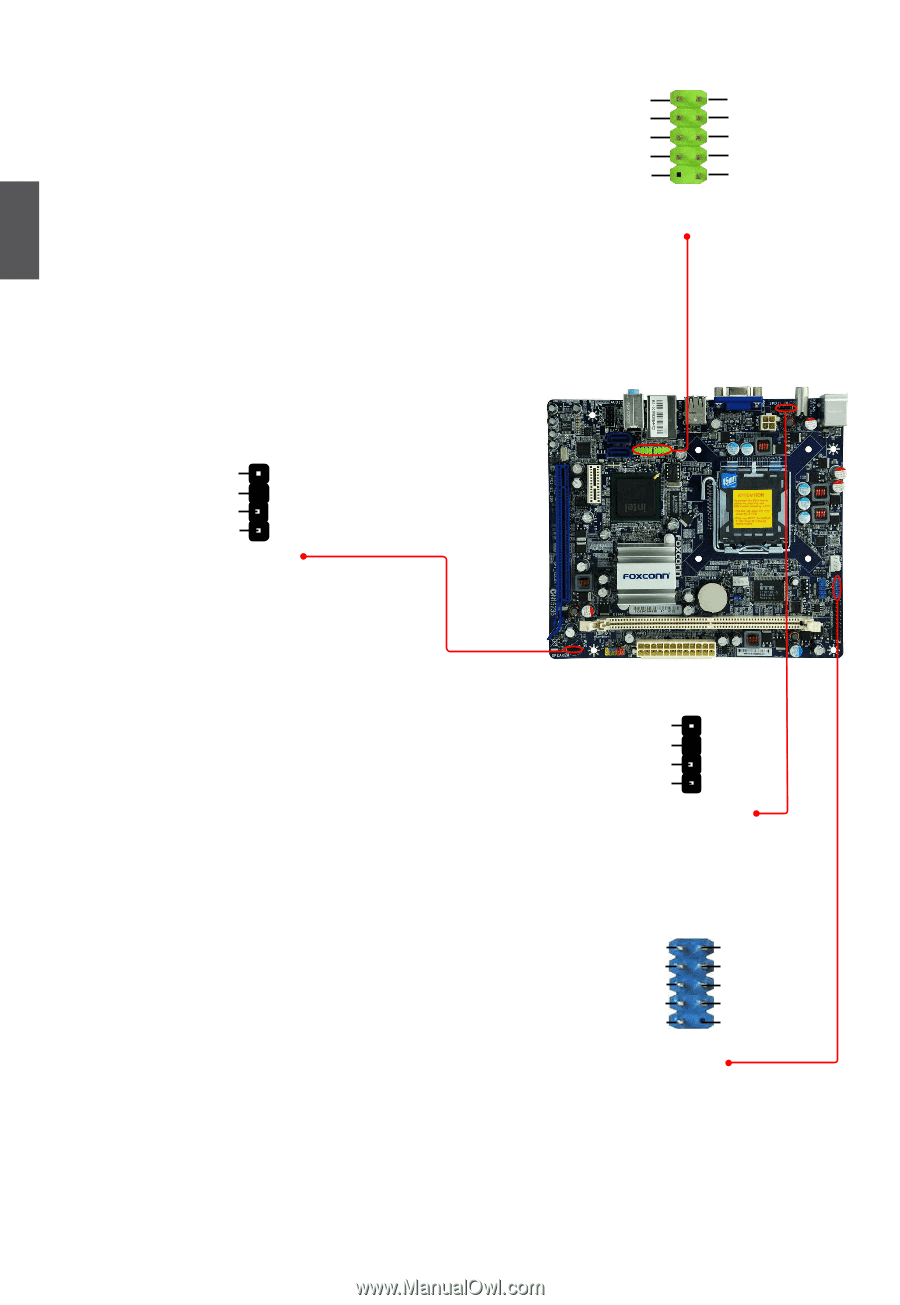
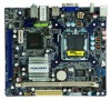
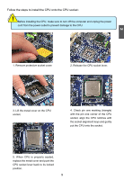
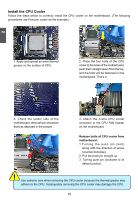
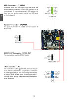
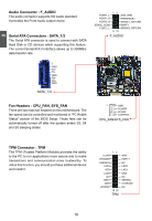
2 USB Connectors : F_USB1/2 In addition to the four USB ports on the rear panel, this product also provides two 10-pin USB headers on its motherboard. By connecting through USB cables with them, user can quickly expand another four USB ports on the front panel. 12 VCC VCC D- D- D+ D+ GND GND EMPTY NC 9 10 F_USB 1/2 Speaker Connector : SPEAKER The speaker connector is used to connect speaker of the chassis. SPKJ 1 EMPTY 2 NC 3 SPKJ 4 SPEAKER S/PDIF OUT Connector : SPDIF_OUT The connector is used for S/PDIF output. LPC Connector : LPC This connector is a debug port. LPC stands for low-pin count, the low-pin count bus can provide a connection for a debugging dongle. The basic design encompasses using a Super I/O and UART on the dongle with a DB9 port out to provide similar debugging capabilities to the serial port. +5V 1 EMPTY 2 SPDIF_OUT 3 GND 4 SPDIF_OUT CK_33MHz RESET LPC_FRAMEJ LPC_AD3 LPC_AD2 12 9 10 LPC LPC_AD1 LPC_AD0 3D3VSB GND EMPTY 14
-
 1
1 -
2
-
3
-
4
-
5
-
6
-
7
-
8
-
9
-
10
-
11
-
12
-
13
-
14
-
15
-
 16
16 -
 17
17 -
 18
18 -
 19
19 -
 20
20 -
 21
21 -
 22
22 -
 23
23 -
 24
24 -
 25
25 -
 26
26 -
27
-
28
-
29
-
30
-
31
-
32
-
33
-
34
-
35
-
36
-
37
-
38
-
39
-
40
-
41
-
42
-
43
-
44
-
45
-
46
-
47
-
48
-
49
-
50
-
51
-
52
-
53
-
54
-
55
-
56
-
57
-
58
-
59
-
60
-
61
-
62
-
63
-
64
-
65
-
66
-
67
-
68
-
69
-
70
-
71
-
72
-
73
-
74
 |
 |