Foxconn H61MXE User manual - Page 24
Jumpers, Clear CMOS Jumper: CLR_CMOS - manual
 |
View all Foxconn H61MXE manuals
Add to My Manuals
Save this manual to your list of manuals |
Page 24 highlights
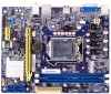
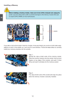
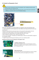
2 2-5 Jumpers For some features needed, users can change the jumper settings on this motherboard to modify them. This section explains how to use the various functions of this motherboard by changing the jumper settings. Users should read the following content carefully prior to modifying any jumper setting. Description of Jumpers 1. For any jumper on this motherboard, pin 1 can be identified by the bold silkscreen next to it. However, in this manual, pin 1 is simply labeled as "1". 2. The following table explains different types of the jumper settings. "Closed" means placing a jumper cap on the two pins to temporarily short them. The shorting can also be done by touching two pins by a screwdriver for a few seconds, but using jumper cap is recommended. It can prevent hazardous ESD (Electrical Static Discharge) problem. Jumper Diagram Definition Description 1 1 1 Closed Open Set Pin 1 and Pin 2 closed Set Pin 1 and Pin 2 O�p�e�n� Clear CMOS Jumper: CLR_CMOS The motherboard uses CMOS RAM to store the basic hardware information (such as BIOS data, date, time information, hardware password...etc.). Clear CMOS data is the fast way to go back to factory default when the BIOS settings were mistakenly modified. The steps to clear CMOS data are : 1. Turn off the computer, unplug the power cord from the power outlet. 2. Put a metal object(such as a screwdriver) onto pins 1-2 to short them. This will clear CMOS data. 3. After a few second, remove the metal object to leave the Pins 1-2 open. 4. Plug in the power cord to your computer and turn it on. 5. Go to BIOS Setup to configure new system as described in next chapter. 1 Clear 2 Normal 1 (Default) 2 CLR_CMOS WARNING! ■ D��i�s�c�o�n�n��e�c�t�t�h�e��p�o��w�e��r�c�a�b��le��b�e��fo�r�e��a�d��ju�s�t�i�n�g��th��e�j�u�m��p�e��r�s�e�t�t�in�g��s�. ■ D��o��n�o�t��c�le��a�r�t�h�e��C�M��O��S��w��h�il�e��th��e��s�y�s�t�e�m��i�s�t�u�r�n�e��d�o��n�. 17
-
 1
1 -
2
-
3
-
4
-
5
-
6
-
7
-
8
-
9
-
10
-
11
-
12
-
13
-
14
-
15
-
16
-
17
-
18
-
 19
19 -
 20
20 -
 21
21 -
 22
22 -
 23
23 -
 24
24 -
 25
25 -
 26
26 -
 27
27 -
 28
28 -
 29
29 -
30
-
31
-
32
-
33
-
34
-
35
-
36
-
37
-
38
-
39
-
40
-
41
-
42
-
43
-
44
-
45
-
46
-
47
-
48
-
49
-
50
-
51
-
52
-
53
-
54
-
55
-
56
-
57
-
58
-
59
-
60
-
61
-
62
-
63
-
64
-
65
-
66
 |
 |