Foxconn Inferno Katana English Manual. - Page 29
Enable ATAPI hardware. Attempt to read from ARMD and ATAPI CDROM.
 |
View all Foxconn Inferno Katana manuals
Add to My Manuals
Save this manual to your list of manuals |
Page 29 highlights
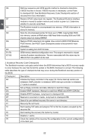
2 D6 D7 D8 D9 DA DC E1-E8 EC-EE Both key sequence and OEM specific method is checked to determine if BIOS recovery is forced. If BIOS recovery is necessary, control flows to checkpoint E0. See Bootblock Recovery Code Checkpoints section of document for more information. Restore CPUID value back into register. The Bootblock-Runtime interface module is moved to system memory and control is given to it. Determine whether to execute serial flash. The Runtime module is uncompressed into memory. CPUID information is stored in memory. Store the Uncompressed pointer for future use in PMM. Copying Main BIOS into memory. Leaves all RAM below 1MB Read-Write including E000 and F000 shadow areas but closing SMRAM. Restore CPUID value back into register. Give control to BIOS POST(Execute POST Kernel). See POST Code Checkpoints section of document for more information. System is waking from ACPI S3 state. OEM memory detection/configuration error. This range is reserved for chipset vendors & system manufacturers. The error associated with this value may be different from one platform to the next. 2. Bootblock Recovery Code Checkpoints The Bootblock recovery code gets control when the BIOS determines that a BIOS recovery needs to occur because the user has forced the update or the BIOS checksum is corrupt. The following table describes the type of checkpoints that may occur during the Bootblock recovery portion of the BIOS: Checkpoint Description E0 Initialize the floppy controller in the super I/O. Some interrupt vectors are initialized. DMA controller is initialized. 8259 interrupt controller is initialized. L1 cache is enabled. E9 Set up floppy controller and data. Attempt to read from floppy. EA Enable ATAPI hardware. Attempt to read from ARMD and ATAPI CDROM. EB Disable ATAPI hardware. Jump back to checkpoint E9. EF Read error occurred on media. Jump back to checkpoint EB. F0 Search for pre-defined recovery file name in root directory. F1 Recovery file not found. F2 Start reading FAT table and analyze FAT to find the clusters occupied by the recovery file. F3 Start reading the recovery file cluster by cluster. F5 Disable L1 cache. FA Check the validity of the recovery file configuration to the current configuration of the flash part. 22 22
-
 1
1 -
2
-
3
-
4
-
5
-
6
-
7
-
8
-
9
-
10
-
11
-
12
-
13
-
14
-
15
-
16
-
17
-
18
-
19
-
20
-
21
-
22
-
23
-
 24
24 -
 25
25 -
 26
26 -
 27
27 -
 28
28 -
 29
29 -
 30
30 -
 31
31 -
 32
32 -
 33
33 -
 34
34 -
35
-
36
-
37
-
38
-
39
-
40
-
41
-
42
-
43
-
44
-
45
-
46
-
47
-
48
-
49
-
50
-
51
-
52
-
53
-
54
-
55
-
56
-
57
-
58
-
59
-
60
-
61
-
62
-
63
-
64
-
65
-
66
-
67
-
68
-
69
-
70
-
71
-
72
-
73
-
74
-
75
-
76
-
77
-
78
-
79
-
80
-
81
-
82
-
83
-
84
-
85
-
86
-
87
-
88
-
89
-
90
-
91
-
92
-
93
-
94
-
95
-
96
-
97
-
98
-
99
-
100
-
101
-
102
-
103
-
104
-
105
-
106
-
107
-
108
-
109
-
110
-
111
-
112
-
113
-
114
-
115
-
116
-
117
-
118
-
119
-
120
-
121
-
122
-
123
-
124
 |
 |