Frigidaire AEQ6000ES Installation Instructions - Page 8
General Installation, Replacement Parts, Gas Connection - review
 |
UPC - 012505374906
View all Frigidaire AEQ6000ES manuals
Add to My Manuals
Save this manual to your list of manuals |
Page 8 highlights
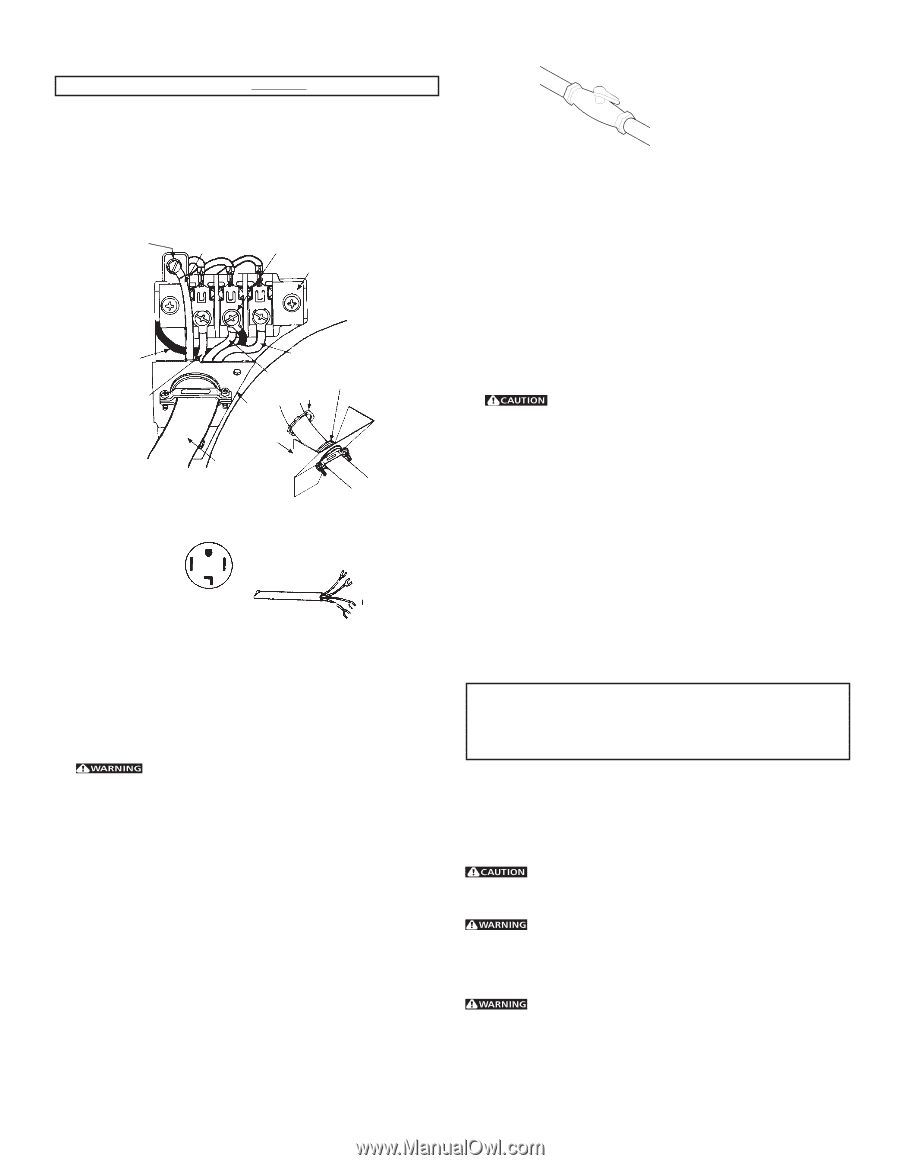
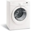
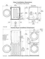
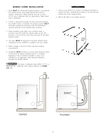
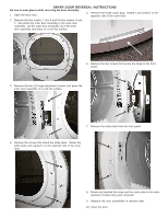
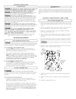
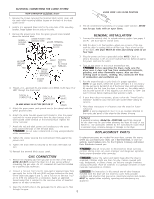
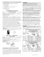
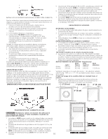
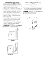
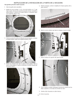
ELECTRICAL CONNECTIONS FOR 4-WIRE SYSTEM NON-CANADIAN ELECTRIC Dryer VALVE OPEN / GAS FLOW POSITION 1. Remove the screws securing the terminal block access cover and the strain relief mounting bracket located on the back of the dryer upper corner. 2. Install a U.L. approved strain relief in the entry hole of the mounting bracket. Finger tighten the nut only at this time. 4. Test all connections by brushing on a soapy water solution. NEVER test for gas leaks with an open flame. 3. Remove the ground wire from the green ground screw located above the terminal block. GREEN GROUND SCREW GREEN POWER CORD GROUND WIRE SILVER TERMINAL TERMINAL BLOCK GENERAL INSTALLATION 1. Connect the exhaust duct to outside exhaust system (see pages 3 and 4). Use duct tape to seal all joints. 2. With the dryer in its final position, adjust one or more of the legs until the dryer is resting solid on all four legs. Place a level on top of the dryer. The dryer MUST be level and resting solid on all four legs. NEUTRAL GROUND WIRE RED BLACK WHITE NUT STRAIN RELIEF MOUNTING BRACKET TIGHTEN NUT TO THESE THREADS POWER CORD 4. Thread a U.L. approved 30 amp power cord, NEMA 14-30 type ST or SRDT through the strain relief. TYPICAL 4 CONDUCTOR TYPICAL 4 CONDUCTOR BLACK WHITE 30 AMP NEMA 14-30 TYPE SRDT OR ST RED GREEN 5. Attach the green power cord ground wire to the cabinet with the green ground screw. 6. Attach the white (neutral) power cord conductor from the power cord and the neutral ground wire from the dryer harness to the silver-colored center terminal on the terminal block. Tighten the screw securely. 7. Attach the red and black power cord conductors to the outer brass-colored terminals on the terminal block. Do not make a sharp bend or crimp wiring/conductor at the connections. 8. Tighten the screws securing the cord restraint firmly against the power cord. 9. Tighten the strain relief nut securely so the strain relief does not turn. 10. Reinstall the terminal block access cover. GAS CONNECTION 1. Remove the shipping cap from gas pipe at the rear of the dryer. NOTE: DO NOT connect the dryer to L.P. gas service without converting the gas valve. An L.P. conversion kit must be installed by a qualified gas technician. 2. Connect a 1/2 inch (1.27 cm) I.D. semi-rigid or approved pipe from gas supply line to the 3/8 inch (0.96 cm) pipe located on the back of the dryer (see pages 6 and 7). Use a 1/2 inch to 3/8 inch (1.27 cm to 0.96 cm) reducer for a connection. Apply an approved thread sealer that is resistant to the corrosive action of liquefied gases on all pipe connections. 3. Plug the power cord into a grounded outlet. NOTE: Check to ensure the power is off at circuit breaker/fuse box before plugging the power cord into the outlet. 4. Turn on the power at the circuit breaker/fuse box. Before operating the dryer, make sure the dryer area is clear and free from combustible materials, gasoline, and other flammable vapors. Also see that nothing (such as boxes, clothing, etc.) obstructs the flow of combustion and ventilation air. 5. Run the dryer through a cycle check for proper operation. NOTE: On gas dryers, before the burner will light, it is n e c e s s a r y for the gas line to be bled of air. If the burner does not light within 45 seconds the first time the dryer is turned on, the safety switch will shut the burner off. If this happens, turn the timer to "OFF" and wait 5 minutes before making another attempt to light. 6. If your dryer does not operate, please review the "Avoid Service Checklist" located in your Use and Care Guide before calling for service. 7. Place these instructions in a location near the dryer for future reference. NOTE: A wiring diagram/tech sheet is in an envelope attached to the inside side panel of the dryer by the blower housing. Pedestal A pedestal accessory, Model No. APWD15W, specifically designed for this dryer may be used when elevating the dryer for ease of use. Failure to use accessories certified by the manufacturer could result in personal injury, property damage or damage to the dryer. REPLACEMENT PARTS If replacements parts are needed for your dryer, contact the source where you purchased your dryer, call 1-800-944-9044, or visit our website, www.frigidaire.com, for the Frigidaire Company Authorized Parts Distributor nearest you. Label all wires prior to disconnection when servicing controls. Wiring errors can cause improper and dangerous operation. Verify proper operation after servicing. Destroy the carton and plastic bags after the dryer is unpacked. Children might use them for play. Cartons covered with rugs, bedspreads, or plastic sheets can become airtight chambers causing suffocation. Place all materials in a garbage container or make materials inaccessible to children. The instructions in this manual and all other literature included with this dryer are not meant to cover every possible condition and situation that may occur. Good safe practice and caution MUST be applied when installing, operating and maintaining any appliance. 3. Open the shutoff valve in the gassupply line to allow gas to flow through the pipe. 8
-
 1
1 -
2
-
 3
3 -
 4
4 -
 5
5 -
 6
6 -
 7
7 -
 8
8 -
 9
9 -
 10
10 -
 11
11 -
 12
12 -
 13
13 -
14
-
15
 |
 |