Frigidaire FASE7021NW Installation Instructions (All Languages) - Page 14
Gas connection, WARNING, IMPORTANT
 |
View all Frigidaire FASE7021NW manuals
Add to My Manuals
Save this manual to your list of manuals |
Page 14 highlights
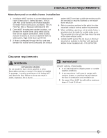
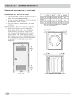
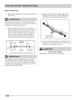
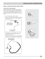
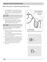
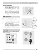
INSTALLATION INSTRUCTIONS Gas connection 1 Remove the shipping cap from gas pipe at the rear of the dryer. IMPORTANT DO NOT connect the dryer to L.P. gas service without converting the gas valve. An L.P. conversion kit must be installed by a qualified gas technician. 2 Connect a 1/2 inch (1.27 cm) I.D. semi-rigid or approved pipe from gas supply line to the 3/8 inch (0.96 cm) pipe located on the back of the dryer. Use a 1/2 inch to 3/8 inch (1.27 cm to 0.96 cm) reducer for the connection. Apply an approved thread sealer that is resistant to the corrosive action of liquefied gases on all pipe connections. Manual Shutoff Flare Valve Union GAS FLOW Flare Union Closed Nipple Open Flexible Connector Inlet Pipe on Back of Dryer All connections must be wrench-tightened IMPORTANT The supply line must be equipped with an approved manual shutoff valve. This valve should be located in the same room as the dryer and should be in a location that allows ease of opening and closing. Do not block access to the gas shutoff valve. 3 Open the shutoff valve in the gas supply line to allow gas to flow through the pipe. Wait a few minutes for gas to move through the gas line. to dryer Shutoff Valve Open position from gas supply 4 Check for gas system leaks with a manometer. If a manometer is not available, test all connections by brushing on a soapy water solution. WARNING EXPLOSION HAZARD NEVER test for gas leaks with an open flame. 14
-
 1
1 -
2
-
3
-
4
-
5
-
6
-
7
-
8
-
 9
9 -
 10
10 -
 11
11 -
 12
12 -
 13
13 -
 14
14 -
 15
15 -
 16
16 -
 17
17 -
 18
18 -
 19
19 -
20
-
21
-
22
-
23
-
24
-
25
-
26
-
27
-
28
-
29
-
30
-
31
-
32
-
33
-
34
-
35
-
36
-
37
-
38
-
39
-
40
-
41
-
42
-
43
-
44
-
45
-
46
-
47
-
48
-
49
-
50
-
51
-
52
 |
 |