Frigidaire FEB24S5AS Installation Instructions (All Languages) - Page 6
Cabinet Installation - 24
 |
UPC - 057112080680
View all Frigidaire FEB24S5AS manuals
Add to My Manuals
Save this manual to your list of manuals |
Page 6 highlights
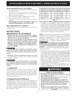
ELECTRIC WALL OVEN INSTALLATION INSTRUCTIONS 5. Cabinet Installation A. 24" and 27", Single and Double Ovens Insert appliance into cutout. Use the screws provided to fasten the front frame of the appliance to the cabinet. The mounting holes in the front frame of appliance may be used as a template to locate the appliance mounting screw holes. To fasten the appliance to the cabinet: 1. Line up the 2 mounting holes on the decorative trim (ventilation) (taped to the oven side panel) with the lower mounting holes on each side of the oven frame, below the oven door (see figure 7). 2. Use 2 screws from the miscellaneous parts bag to secure the decorative trim (ventilation) and appliance to the cabinetry. 3. Use the remaining 2 screws for mounting the appliance in the upper two mounting holes on each side of the oven frame, above the door. MOUNTING SCREW DECORATIVE TRIM (VENTILATION) MOUNTING SCREW Figure 7 B. 30", Single and Double Ovens The wall oven can tip when the door is open. The mounting brackets supplied with the wall oven must be attached to the cabinet and the appliance to prevent tipping of the wall oven and injury to persons. Mounting Brackets Installation Instructions 1.Unpack the wall oven and find the 2 mounting screws included in the literature package. The door may be removed to facilitate handling (see the Owner's Guide for instructions). 2.The mounting brackets are temporarily installed under the decorative side trims of the oven when shipped (see Figure 8 or 9 ). Remove the mounting brackets from the unit side frame using a No. 2 Robertson® screw driver (square drive preferred, however a No. 2 Phillips® or Quadrex® screw driver can also be used). Open the door to remove the screws, located at the upper end of the side trim. 6 Cutout Dimensions 28 1/2" (72.4 cm) Min.* 29" (73.7 cm) Max.* 28 1/16" (71.3 cm) Min. 29 5/8" (75.2 cm) Max. Mounting Brackets 22" (55.9 cm) 21 1/4" (54.0 cm) 27 1/4" (71.8 cm) Min. 28 7/8" (73.3 cm) Max. Wood Shims (If Needed) * Recommended Cutout Width is 28 1/2" (72.4 cm) Figure 8 30" SINGLE OVEN Cutout Dimensions 28 1/2" (72.4 cm) Min.* 29" (73.7 cm) Max.* 28 1/16" (71.3 cm) Min. 29 7/16" (74.8 cm) Max. Mounting Brackets 42 3/4" (108.6 cm) 42" (106.7 cm) 49 1/8" (124.8 cm) Min. 49 3/4" (126.4 cm) Max. Wood Shims (If Needed) * Recommended Cutout Width is 28 1/2" (72.4 cm) Figure 9 30" DOUBLE OVENS
-
 1
1 -
 2
2 -
 3
3 -
 4
4 -
 5
5 -
 6
6 -
 7
7 -
 8
8 -
 9
9 -
 10
10 -
 11
11 -
 12
12 -
13
-
14
-
15
-
16
-
17
-
18
-
19
-
20
-
21
-
22
-
23
-
24
 |
 |
