Frigidaire FEQ1442ES Installation Instructions - Page 7
Electrical Installation, Grounding Requirements, Electrical Connections, For 3-wire System, For 4- - electric dryer manual
 |
UPC - 012505373824
View all Frigidaire FEQ1442ES manuals
Add to My Manuals
Save this manual to your list of manuals |
Page 7 highlights
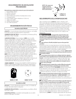
ELECTRICAL INSTALLATION ELECTRIC Dryer The following are specific requirements for proper and safe electrical installation of your dryer. Failure to follow these instructions can create electrical shock and/or a fire hazard. This appliance MUST be properly grounded. Electrical shock can result if the dryer is not properly grounded. Follow the instructions in this manual for proper grounding. Do not use an extension cord with this dryer. Some extension cords are not designed to withstand the amounts of electrical current this dryer utilizes and can melt, creating electrical shock and/or fire hazard. Locate the dryer within reach of the receptacle for the length power cord to be purchased, allowing some slack in the cord. Refer to the pre-installation requirements in this manual for the proper power cord to be purchased. A U.L. approved strain relief must be installed onto power cord. If the strain relief is not attached, the cord can be pulled out of the dryer and can be cut by any movement of the cord, resulting in electrical shock. Do not use an aluminum wired receptacle with a copper wired power cord and plug (or vice versa). A chemical reaction occurs between copper and aluminum and can cause electrical shorts. The proper wiring and receptacle is a copper wired power cord with a copper wired receptacle. NOTE: Dryers operating on 208 volt power supply will have longer drying times than operating on 240 volt power supply. GROUNDING REQUIREMENTS ELECTRIC Dryer GREEN GROUND SCREW NEUTRAL GROUND WIRE SILVER TERMINAL NUT TIGHTEN NUT TO THESE THREADS STRAIN RELIEF MOUNTING BRACKET POWER CORD 7. Tighten the screws securing the cord restraint firmly against the power cord. 8. Tighten the strain relief nut securely so that the strain relief does not turn. 9. Reinstall the terminal block cover. GREEN GROUND SCREW GREEN POWER CORD GROUND WIRE SILVER TERMINAL TERMINAL BLOCK Improper connection of the equipment grounding conductor can result in a risk of electrical shock. Check with a licensed electrician if you are in doubt as to whether the appliance is properly grounded. For a grounded, cord-connected dryer: 1. The dryer MUST be grounded. In the event of a malfunction or breakdown, grounding will reduce the risk of electrical shock by a path of least resistance for electrical current. 2. If your dryer is equipped with a power supply cord having an equipment-grounding conductor and a grounding plug, the plug MUST be plugged into an appropriate, copper wired receptacle that is properly installed and grounded in accordance with all local codes and ordinances. If in doubt, call a licensed electrician. Do not modify plug provided with the appliance. For a permanently connected dryer: 1. The dryer MUST be connected to a grounded metal, permanent wiring system; or an equipment grounding conductor must be run with the circuit conductors and connected to the equipment-grounding terminal or lead on the appliance. GAS Dryer This dryer is equipped with a three-prong (grounding) plug for your protection against shock hazard and should be plugged directly into a properly grounded three-prong receptacle. Do not cut or remove the grounding prong from this plug. ELECTRICAL CONNECTIONS FOR 3-WIRE SYSTEM NEUTRAL GROUND WIRE RED BLACK WHITE NUT STRAIN RELIEF MOUNTING BRACKET TIGHTEN NUT TO THESE THREADS POWER CORD ELECTRICAL CONNECTIONS FOR 4-WIRE SYSTEM ELECTRIC Dryer 1. Remove the screws securing the terminal block access cover and the strain relief mounting bracket located on the back of the dryer upper corner. 2. Install a U.L. approved strain relief in the entry hole of the mounting bracket. Finger tighten the nut only at this time. 3. Remove the ground wire from the green ground screw located above the terminal block. 4. Thread a U.L. approved 30 amp power cord, NEMA 14-30 type ST or SRDT through the strain relief. ELECTRIC Dryer TYPICAL 4 CONDUCTOR TYPICAL 4 CONDUCTOR BLACK WHITE 1. Remove the screws securing the terminal block access cover and the RED strain relief mounting bracket located on the back of the dryer upper corner. 30 AMP NEMA 14-30 TYPE SRDT OR ST GREEN 2. Install a U.L. approved strain relief into the power cord entry hole of the mounting bracket. Finger tighten the nut only at this time. 5. Attach the green power cord ground wire to the cabinet with the green ground screw. 3. Thread a U.L. approved 30 amp. power cord, NEMA 10-30 type SRDT, through the strain relief. 6. Attach the white (neutral) power cord conductor from the power cord and the neutral ground wire from the dryer harness to the silver- 4. Attach the power cord neutral (center wire) conductor to the silver colored center terminal on the terminal block. Tighten the screw colored center terminal on the terminal block. Tighten the screw securely. securely. 5. Attach the remaining two power cord outer conductors to the outer 7. Attach the red and black power cord conductors to the outer brasscolored terminals on the terminal block. brass colored terminals on the terminal block. Tighten both screws securely. Do not make a sharp bend or crimp wiring/ conductor at the connections. Do not make a sharp bend or crimp wiring/ conductor at connections. 8. Tighten the screws securing the cord restraint firmly against the power cord. 6. Reattach the strain relief mounting bracket to the back of the dryer 9. Tighten the strain relief nut securely so the strain relief does not turn. with two screws. Tighten screws securely. 7 10. Reinstall the terminal block access cover.
-
 1
1 -
 2
2 -
 3
3 -
 4
4 -
 5
5 -
 6
6 -
 7
7 -
 8
8 -
 9
9 -
 10
10 -
 11
11 -
 12
12 -
13
-
14
-
15
-
16
 |
 |
